
Fig. 1.
Title: Elementary Course in Woodwork
Author: George Alexander Ross
Release date: October 26, 2021 [eBook #66616]
Most recently updated: October 18, 2024
Language: English
Credits: Charlene Taylor and the Online Distributed Proofreading Team at https://www.pgdp.net (This file was produced from images generously made available by The Internet Archive/American Libraries.)
DESIGNED FOR USE IN HIGH
AND TECHNICAL SCHOOLS
WITH
ONE HUNDRED AND THIRTY-FOUR ILLUSTRATIONS
BY
GEORGE ALEXANDER ROSS
INSTRUCTOR IN
WOODWORK AND PATTERNMAKING
LEWIS INSTITUTE, CHICAGO
FIRST EDITION
A. FLANAGAN COMPANY
CHICAGO :: NEW YORK
Copyright, 1901
by
A. Flanagan Company
The character and object of this book is set forth on its title page. It is a manual designed principally for the practical assistance of students in elementary woodwork in the Lewis Institute.
The author has endeavored to present the subject in such a manner as to make simple the transition from the easier to the more difficult operations; the exercises have been selected after having had a thorough test covering a period of three years, and will be found practical in their application to the students in High and Technical Schools in elementary woodwork and turning.
Part one, the bench work, is intended to cover a period of eight weeks, two hours per day, and part two, wood turning, four weeks, two hours per day, thus making a course which will be found to touch the principal points in elementary work, at the same time giving practice in the uses of the tools most commonly used in carpentry, joinery and wood turning. Disston & Sons’ Handbook for Lumbermen has furnished many of the facts presented under “Care of Saws.”
It has been the author’s aim in this course to give just enough instruction in the work so that the student might be led to study out the problems for himself; by this means he is able to study the course of work that follows the second part of this book, i. e., Pattern Making.
A cursory perusal of the work will disclose many features which the author feels sure will commend themselves to instructors and others interested in this department of school work, and with the hope that these pages may prove a valuable aid to students and teachers alike, this work is presented to the public.
Lewis Institute, Chicago, 1901.
| PAGE. | |
| Care of Saws and Equipment | 7 |
| Exercise in Sawing and Planing | 21 |
| The Halved Joint | 47 |
| The Mortise and Tenon Joint | 51 |
| Keyed Mortise and Tenon with Brace | 57 |
| Exercise with the Bench, Bead, Rabbet, and Molding Planes |
62 |
| Blind Mortises and Tenons with Beading and Rabbeting |
66 |
| Dovetail Corner Joint (Common) | 71 |
| Glass Panel Door Frame | 79 |
| Bench Hook. Use of Shellac | 87 |
| Box with Sliding Top | 89 |
| Problem in Truss Work | 94 |
| Problem in Stair Building | 100 |
| Problem in Stair Railing | 106 |
| To Prepare Shellac | 114 |
| To Prepare Glue and How to Use It | 115 |
| To True Oil Stones | 116 |
Elementary woodwork can be more readily learned from small pieces of wood than from large; so the exercises that are here given are of such dimensions that they can be easily handled in working out the problems.
Since it is by what we study and learn that we are able to do something else, the student in beginning this work should thoroughly familiarize himself with the tools, their names and uses, so that he may more readily understand their application in the work that follows.
The equipment for the general use of students in each bench locker is as follows:
| 1 | 20-inch Rip-Saw. |
| 1 | 20-inch Cross-Cut Saw. |
| 1 | 10-inch Back-Saw. |
| 1 | 8-inch Try-Square. |
| 1 | 8-inch Bevel. |
| 1 | 8-inch Wing Dividers. |
| 1 | Marking Knife. |
| 1 | ⅜-inch Hand Mortising Chisel. |
| 1 | Bit Brace. |
| 1 | ¼-inch, ⅜-inch, ½-inch and ¾-inch Auger Bit. |
| 1 | Nail Set. |
| 1 | Mallet. |
| 1 | Hammer. [Pg 8] |
| 1 | Oil Stone. |
| 1 | Oil Can. |
| 1 | Screw Driver. |
| 1 | Dust Brush. |
The equipment of tools in drawer and under the care of individual students is as follows:
| 1 | Number 5 Bailey Iron Plane (Jack-Plane). |
| 1 | Number 4 Bailey Iron Plane (Smooth-Plane). |
| 1 | Marking Gauge. |
| 1 | ¼-inch, ½-inch, ¾-inch, and 1-inch Bevel Edge Paring Chisel. |
| 1 | ¼-inch and ¾-inch Skew Turning Chisel. |
| 1 | ¼-inch and ¾-inch Turning Gouge. |
Tools, such as molding, beading, rabbeting, and plow planes are found in the tool room, and are issued to students on check when required.

Fig. 1.
Fig. 1 shows the double bench equipped with rack, cam and quick acting vises, with the locker for the general tools and four drawers on each [Pg 9] side of the bench with tools for the use of the individual student. Carpenters’ benches are usually about 33 inches high, while cabinet and pattern makers’ benches are from 2 inches to 4 inches higher.
The careful workman as a rule takes great pride in the condition in which his bench is kept; so the beginner should see that his immediate surroundings are kept in a neat, workmanlike manner, and with everything in proper place.
Care should be taken to protect the top of the bench from injury; it should never be marked by the chisel or cut by the saw. If chiseling has to be done on the bench, place the work on the bench hook or on a board, and in sawing use a bench hook such as is shown in Fig. 2, that has a side lip that will protect the bench top.

Fig. 2.
The bench hook is made by students as an exercise, and is used to replace those hooks that have become worn out.
The material, which is delivered from the lumber yard in boards or planks, has to be cut up into lengths and widths suitable for the work to be done. The tools used for doing this cutting are the rip-saw and the cross-cut saw.
Now, a great amount of time can be lost in this work by the student, for the reason of his trying to do work with one tool when another should be used, and especially is this so in regard to saws. A saw will [Pg 10] cut faster than a chisel in some places, and sometimes make the work as good if not better; so the student should learn to file and to keep a saw in just as good order as any other tool used.
We devote considerable space here to the saw, for we feel that the saw as one of the principal tools is often neglected, and is not used by students in their work as much as it should be. By a judicious use of this tool much time can be saved and a greater amount of ground covered than by trying to use a chisel or a jack knife in its stead.
Saws are either reciprocating or continuous in action; the first being a flat blade and a practically straight edge, making a plane cut, as in mill, jig, and sash saws; the latter either a circular or rotating disc, cutting in a plane at right angles to its axis (see buzz-saw in shop) or a continuous ribbon or band running on two pulleys, making a plane or curved cut with a straight edge parallel to their axis of rotation (see band-saw in shop).
Practically speaking, the teeth are a series of knives set on a circular or straight line, each tooth cutting out its proportion of wood, and kept from cutting more by the teeth on either side of it. Each tooth should cut the same amount and carry out the chips or dust, dropping it to the side or below the material being sawed. Different kinds of woods require teeth different in number, angle or pitch, and style of filing.
The perfect saw is one that cuts the fastest and smoothest with the least expenditure of power; to do this it is evident that each tooth [Pg 11] should be so constructed and dressed as to do an equal proportion of the work, for if any of the teeth are out of line or shape they are not only useless themselves but a disadvantage to the others.
A saw tooth has two functions—paring and scraping. A slitting or rip saw for wood should have its cutting edge at about right angles to the fibre of the wood, severing it in one place, the throat of the tooth wedging out the piece.
Fig. 3.

The rip-saw, Fig. 3, should be filed square across, and the front or rake of tooth should be at about right angles to the edge of the saw.
After jointing and setting, file one half the teeth from each side, which will give to the cutting edge of the tooth the slight bevel it should have for soft wood; for medium hard woods use a finer toothed saw, and file in the same manner; for the very hard, tough and cross-grained woods, use a saw still finer with the teeth filed slightly beveling, as ripping cross-grained stuff partakes a little of the nature of cross-cutting.
In all cases where ripping is done, the thrust of a saw should be on an angle of about 45 degrees to the material being cut, as shown in Fig. 4. [Pg 12] This makes a shearing cut, an advantage that can be quickly demonstrated with an ordinary pocket knife, cutting any piece of soft wood.
Saws are designated by the number of points or teeth per inch, and the selection of a saw depends upon the character of wood to be worked. A rip-saw should have from 4 to 10 teeth per inch, the cross-cut saw from 6 to 16 teeth per inch. This includes the back-saw, it being filed the same as a regular cross-cut saw.
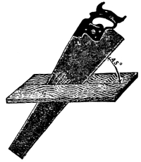
Fig. 4.
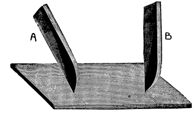
Fig. 5.
The harder the wood, the greater the number of teeth the saw should have.
We will now consider the cross-cut saw tooth in regard to rake or pitch; this being one of the most important features, too much care cannot be taken to have the correct amount of pitch for the duty required. To illustrate this. Fig. 5 represents a board, across which we wish to make a deep mark or score with the point of a knife. Suppose [Pg 13] we hold the knife nearly perpendicular as at B; it is evident that it will push harder and will not cut as smoothly as if it were inclined forward as at A. It follows then that the cutting edge of a cross-cut saw should incline forward as at C, Fig. 6, rather than stand perpendicular as at D, Fig. 7.
Fig. 6.
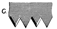
Fig. 7.

Too much hook or pitch and too heavy a set are very common faults, not only detrimental to good work but ruinous to the saw; in the first case, by having a large amount of pitch, the saw takes hold so keenly that frequently it “hangs up” suddenly in the thrust—the result, a kinked or broken blade; in the second, by having too much set, the strain caused by the additional and unnecessary amount of set is out of proportion to the strength of the blade, and it is broken in the same manner. The most general value of pitch used is 60 degrees, though this may be varied a little, more or less, to advantage, as occasion may demand.
In all cases the size of tooth depends largely upon the duty required; a long tooth has the demerit of being weak and liable to spring, but the merit of giving a greater clearance to the saw-dust. The throat space in front of each tooth must be large enough to contain the dust [Pg 14] of that tooth from one stroke; the greater the feed the deeper the dust chamber required, or the more teeth. Where the teeth are fine the shape of the throat is of special interest.
The teeth of a hand-saw should be filed so true that on holding it up to the eye and looking along its edge, it will show a central groove down which a fine needle will slide freely the entire length. This groove must be angular in shape and equal on each side, or the saw is not filed properly and will not run true.
Fig. 8.

Fig. 9.
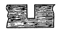
Fig. 10.
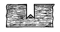
Fig. 11.
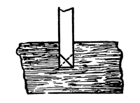
Fig. 8 shows how the groove should appear on looking down the edge of the saw. The action should be such that the bottom of the cut or kerf will present the appearance as shown in Fig. 9, and not as in Fig. 10; the cutting action is shown in Fig. 11, the cutting being done with the outside of the tooth; the fibre of the wood is severed in two places, and the wood is crumbled out from point to point by the thrust of the saw.
The proper amount of bevel is very important, as is demonstrated by the above figures, for if too much bevel is given the points will score so deeply that the fibres severed from the main body will not crumble out as severed but will be removed by continued rasping. This is true, particularly in hard woods, as they require less bevel, as well as pitch, than soft wood. [Pg 15]
The next point to be considered is the bevel or fleam of the point. In Fig. 12 the filer, as in all cases, files from the heel to the point; which is the only correct way.
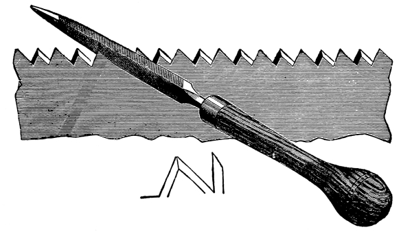
Fig. 12.
The file is supposed to be perpendicular to the side of the saw in the vertical plane (see Fig. 13), at an angle of about 45 degrees in the horizontal plane, measuring from file line towards heel (see Fig. 14).
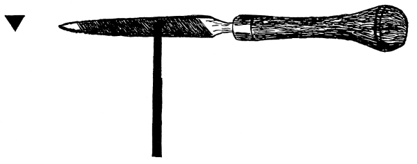
Fig. 13.
Fig. 15 is a fair representation of many saws that we have seen owned [Pg 16] by workmen; the result of owning such tools is shown in the poor work turned out by them.
Fig. 14.

As has already been said, the filing should be done from the heel of the saw toward the point. Many practical saw filers contend that this is wrong; that the filing should be done from the point of the saw toward the handle; but the only support they offer for this theory is that they do away with the feather edge that the filing from the heel of saws puts on the cutting face of the tooth. The feather edge is no objection, as the main part of it is removed when the teeth are side-dressed after the saw is set and sharpened. [Pg 17]
Against the correctness of filing from point to handle may be cited the following objections:
Where a different angle of back is required (it should be remembered that that angle of face should be the same in nearly all cross-cut hand saws, and that angle of back governs angle of point) it will be found very difficult to obtain it without changing the angle of face of the tooth, and as the cutting duty is on the long side of the face, any change is, of course, of great influence. Again, to file from the point of the saw it is necessary to file with the teeth bent toward the operator. This will cause the saw to vibrate or chatter, a thing which not only renders good, clean, even filing impossible, but breaks the teeth off the file.
Fig. 15.

The setting of a saw is an important part of the work in keeping a saw in order, and should be done AFTER the saw has been jointed, and before filing.
The set should be uniform throughout, as the good working of a saw depends nearly as much on this as on the filing. One great mistake is often made in setting a saw, and that is that many try to put the set [Pg 18] in the blade instead of in the tooth. The set should not go at the most lower than half the length of the tooth; by going lower it is liable to spring the body of the saw, if not break the tooth out.
Two methods may be given for setting saws. The first, or old method (employed before saw-sets were invented, and still used by old mechanics) is to take a hardwood block, lay the saw on it, and with a nail set and hammer set every other tooth on the side, then turn the blade over and repeat the operation on the teeth missed from the first side. It is needless to make any comment on this method when saw sets can be bought that are absolutely reliable in their operation.
The second method is to use the saw-set. Saw-sets are made in many styles, and can be bought at any hardware store.
Fig. 16.
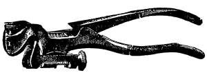
Fig. 17.
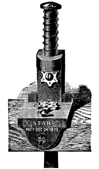
Figs. 16 and 17 show two styles of saw-sets; much might be said in favor of each.
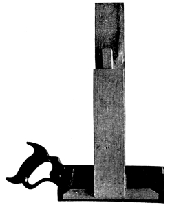
Saw clamps or vises used to hold the saw when filing can be bought (see Fig. 18), but a simple homemade vise can be put together by means of two pieces of board, one 3 feet 6 inches long and 6 inches wide, and [Pg 19] one 2 feet 4 inches long and 6 inches wide. By fastening a piece 2½ inches thick about 10 inches from the top of each, to act as a fulcrum, and fastening a piece on each board at the top to act as jaws, and using a wedge at the bottom to tighten it up, a very serviceable vise is obtained (see Fig. 19).
Fig. 18.
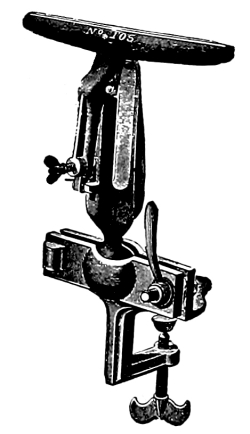
Fig. 19.
To assist those not skilled in the art of filing, there is made a saw-filing clamp with a guide, of which a cut is here shown in Fig. 20.
A few general rules may be observed in saw-filing: See that the file is held at the same angle throughout the operation. File every other tooth on one side, and when filed, reverse the saw and file the other teeth from the other side. For rip saws, place the file at right angles with the saw, and file the rake of tooth at right angles to the edge. After a saw is properly set and filed, lay it on a flat board and rub over the points of the teeth on the sides with an oil stone; this will [Pg 20] regulate the set and insure smooth cutting, making the filing last longer. Should the saw not run true take another cut with the oil stone over the side toward which it leads.

Fig. 20.
A fast cutting cross-cut saw should have deep teeth.
Much useful information on saws can be obtained from a small book published and issued by Disston & Sons, Philadelphia, entitled “Hand Book for Lumbermen,” which, I believe, can be obtained on application.
The other tools used in this course will be taken up in order as they are used in the work.
[Pg 21]
The following operations are designed to give the student a training in the use and care of the most commonly used carpenters’ and joiners’ tools. It is not intended that the student will be able to finish each exercise in one trial, as mistakes will be very common at the beginning, and it is advised that at least two or three trials may be given for the practice and training involved.
In Fig. 21 is shown the working drawing (mechanical drawing) of a rectangular block of wood, and before we proceed to do the work required to finish this, we will study the drawing.
In order to represent solid figures with their three dimensions, length, breadth, and thickness, on a plane surface, i.e., a sheet of paper, we must have at least two drawings (projections), but to simplify the reading still further a third drawing is given, sometimes with additional drawings in the form of cross-sections.
To understand fully the principle upon which a working drawing is made, we will suppose that two transparent planes cross each other at right angles, making four right angles as shown in Fig. 22, (these angles to be known as the 1st, 2nd, 3rd, and 4th angle of the co-ordinate planes), and respectively called the Horizontal and the Vertical planes. [Pg 22]

Fig. 21.
[Pg 23] Two of these angles are used in practice, the 1st and the 3rd; the most modern practice is to use the 3rd, although the 1st is still used in some manufacturing establishments and by some teachers.

Fig. 22.
We will take, first, the 1st angle, and compare it with the results obtained from the 3rd angle. We place the solid (exercise 1) in space in the 1st angle, and also place a similar one in the 3rd angle (see Figs. 23 and 24). [Pg 24]

Fig. 23.
[Pg 25]

Fig. 24.
[Pg 26] By projecting the lines back on the vertical, and down on the horizontal plane, we obtain two views which are respectively the elevation on the vertical and the plan on the horizontal plane; to obtain the third view or end elevation, we have another plane placed perpendicular to planes H and V, as shown in Figs. 23 and 24, and the lines projected back from the left end; by opening or revolving these planes into one plane, as shown in Fig. 25, we have a working drawing made in the 1st angle.
Fig. 25.

Referring to Fig. 24, where we placed the solid in the 3rd angle, we project the lines up on the horizontal and to the front on the vertical plane, and by placing another plane at the end, perpendicular to the H and V planes, we obtain the third projection. Revolving the planes into one plane (i. e., a sheet of paper) Fig. 26, we have the working drawing in the third angle. Compare the results obtained, and note the difference in the reading of the drawing. [Pg 27]
In the first angle we see the plan is below the elevation, and in the third angle the plan is above; the pieces cut out of the exercise may also be noted in the end projection by the lines passing through the center of the exercise; in the first angle the line comes out full, the end being exposed, and in the third angle the surface is behind the full end and shows a dotted line.
Lines that are seen are shown as full lines.

Fig. 26.
Lines that are below a surface and are required in the reading of a drawing are shown as dotted lines.
The drawing, Fig. 21, calls for a piece that is 8 inches at its longest, 2 inches at its widest, and 1 inch at its thickest point, and that may be designated thus: piece 8 inches × 2 inches × 1 inch finished.
For measuring, a standard rule 2 feet long that can be folded up is preferred. The rule is divided into feet, inches, ½ inches, ¼ inches, [Pg 28] ⅛ inches, ¹/₁₆ inches, etc. On some rules will be found scales that can be used in measuring drawings that are drawn to scale. The drawing may be of any scale, using ⅛, ¼, 1, 1½, 3, or 6 inches to the foot.

Fig. 27.
The first thing to be done toward carrying out the work is to saw out a piece from the plank that is laid on the saw trestles (Fig. 27). Mark with a pencil the lines to be sawed; holding the rule in the left hand, and the pencil in the right, and placing the index finger of the left hand against the edge of the plank, as shown in Fig. 28, draw both hands toward the body, thus marking out the piece lengthwise; then measure the length required and place the try-square (Fig. 29) against the edge of the plank, and draw a line along the blade through the point marked.
The piece should be marked out larger than the finished exercise so [Pg 29] that there will be stock enough in the piece to perform the operations required, say 8½ inches × 2½ inches, the plank being thick enough to provide for the work on the sides.

Fig. 28.
Having “laid out” the piece on the plank, take the rip-saw and hold it as shown in Fig. 30: saw down the line, taking care that the “kerf” is square to the side of the plank; then take the cross-cut saw, and saw across the line marked. Hold the cross-cut saw as in Fig. 30.
After having cut the piece from the plank take the jack-plane and put it in good condition for work. A sectional view of the Bailey Iron Plane is shown in Fig. 31, and the parts are as follows: [Pg 30]

Fig. 29.
The plane-iron should be ground on the grindstone if nicked or rounded.
To grind the plane-iron it should be held in the hand as shown in Fig. 32. [Pg 31]
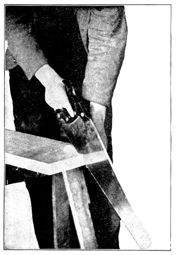
Fig. 30.
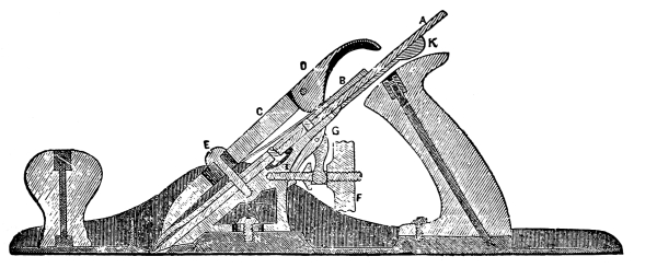
Fig. 31.
[Pg 32] Apply the iron to the stone, as indicated by dotted line A, Fig. 33; then raise it until the proper angle is reached, a position indicated by full lines B.
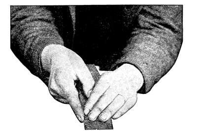
Fig. 32.
Move the tool gradually from one side of the stone to the other. See that there is plenty of water on the stone. The tool should be held during the operation so that it revolves toward the person grinding. The tool thus held is not so liable to have a “wire edge” as it is if held on the stone while it is revolving away from the operator.
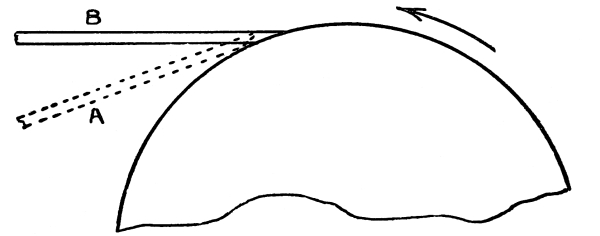
Fig. 33.
The “whetted” edge should never be ground away unless the plane-iron is in very poor condition. [Pg 33]
The grinding is complete when the bevel reaches the cutting edge,—a condition which can readily be determined by holding the finger along the flat side of the iron and having the light fall in the proper direction; a thin bright line will be seen which will determine whether the iron is ground enough. The plane-iron is shown before it is ground in Fig. 34, and Fig. 35 shows it after it is ground.

Fig. 34.

Fig. 35.
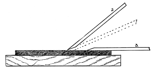
Fig. 36.
To whet or sharpen the iron an oil stone is used. Oil stones are of different grades; a stone of medium hardness is best, as it will cut a little faster and leave a fairly smooth edge; whereas if the stone be hard much time is required to whet the iron, but it leaves a smoother [Pg 34] edge. A coarse stone leaves a rough edge. Use oil that will not become gummy on the stone. Several good artificial stones have lately come on the market which give good service. To sharpen the iron, apply it as shown in Fig. 36, 1 and 2, and move it back and forth as indicated in Fig. 37.
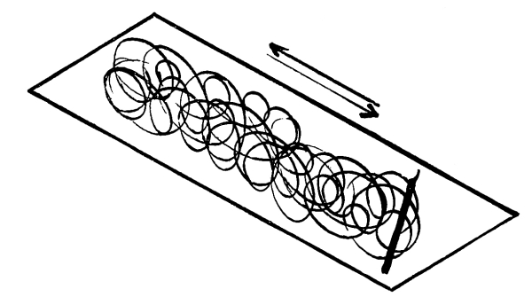
Fig. 37.
Many persons sharpen their plane irons as indicated in Fig. 38; at first thought this may appear to be right, but many mechanics of long experience sharpen the “iron” as indicated in Fig. 36. This method gives a stronger edge, which is not so liable to get nicked when the iron strikes a knot or a hard spot in the work.
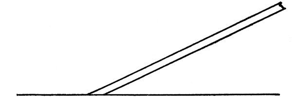
Fig. 38.
Great care should be taken to avoid giving the iron a rocking motion on the oil stone, as this will round the edge and the iron will not be any sharper than it would be if it were in the form shown in Fig. 39. [Pg 35]
Fig. 39.
Fig. 40.

After having whetted the bevel side of the iron sufficiently, turn the iron so that it will rest perfectly flat on the stone, as shown at 3, Fig. 36, and whet it in this position; this will remove the “wire edge.” Care should be taken to see that the iron is not raised in whetting the flat side; if raised as in Fig. 40 the cutting qualities of the edge will be injured.
The iron is now sharpened. Replace the cap iron, keeping it back from ¹/₆₄ to ¹/₃₂ of an inch from the cutting edge; then place it in position and fasten it; look down the face of the plane and see that the edge protrudes far enough to cut the required thickness. The adjustments are made by the thumb screw F and lever K, Fig. 31.
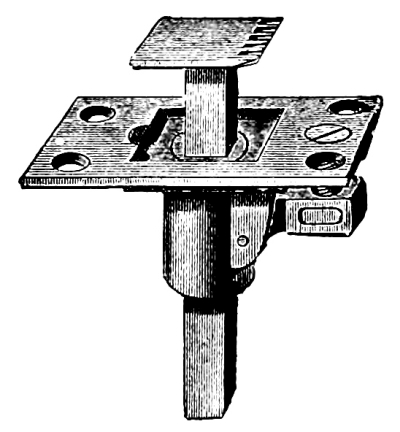
Fig. 41.
Place the block already sawed on the bench against the bench stop, Fig. 41, and then follow the method here given for planing a piece to the given dimensions.
Plane one side true and mark (0) for the “working face.” (A surface is [Pg 36] said to be true when it is perfectly straight across; straight lengthwise, and free from twist).
“Side” here used means one of the wider surfaces in distinction from the narrower surface, the edge.
Methods for testing the surface with parallel strips, etc., will be shown by the instructor.
Plane one edge perfectly straight lengthwise, and square to the face side. Mark this edge for the “working edge”; use the try-square, Fig. 29, to test the work.

Fig. 42.
Set the gauge, Fig. 42, to the width given in the drawing, and gauge a line from the face edge on both sides; then plane to the gauge lines.
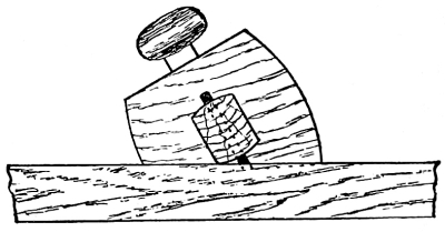
Fig. 43.
In using the gauge see that it is held as shown in Fig. 43, and push away from the body, having the pressure on the gauge as shown by the line A, B, Fig. 44. This will keep the head of the gauge close to the work. Do not try to mark a line by holding it as in Fig. 45, [Pg 37] with the spur at right angles to the work, as it will generally follow the fibre of the wood and a crooked, ragged line will be the result. By holding it as shown in Fig. 43 (and gently letting the spur touch the work, going over it once or twice until the line is of the desired heaviness to work to) a clear, clean-cut line will be obtained.
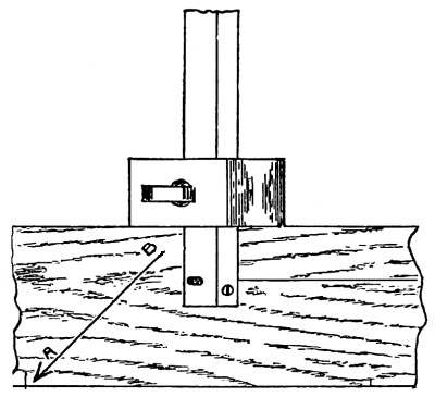
Fig. 44.
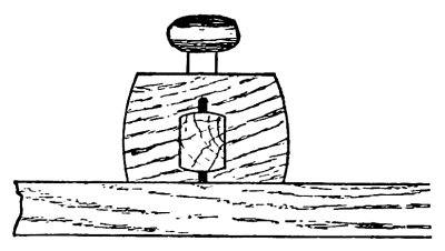
Fig. 45.
Set the gauge to the given thickness (see drawing for dimension) and gauge a line on both edges from face side; then plane to gauge lines. This, if done correctly, will finish the four surfaces. It is sometimes necessary that the ends of a piece of work should be finished smooth; the method of procedure is as follows:
Mark (from one end about ¹/₆₄ of an inch) a knife line all around (see Fig. 46), placing the head of the try-square against the face edge and the face side only; then take a small block and put behind the exercise as shown in Fig. 47, fasten in the vise, and plane to the knife lines. This block will save the corners from breaking. [Pg 38]
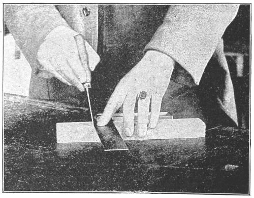
Fig. 46.
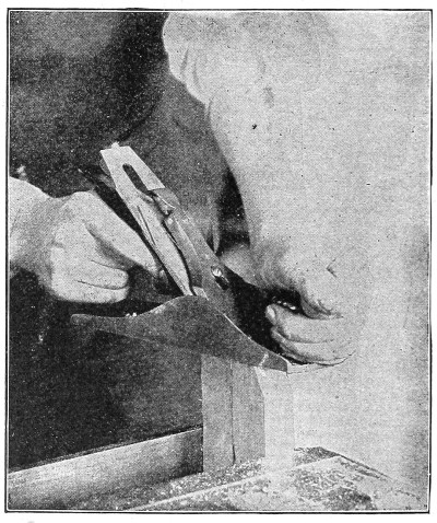
Fig. 47.
[Pg 39] To finish the other end measure the length and mark as on the first end. Then if the piece is too long to plane, saw off near the line, using the back-saw as shown at Fig. 54, and then finish with the plane to the lines.

Fig. 48.
In planing care must be taken to see that the plane is held firmly on the work to secure a true surface. A rocking motion must be avoided. In order to get the best results see that the front of the plane is held down with the left hand, also pressing down and forward with the right hand at the same time, and at the end of the stroke lift the front of the plane as shown in Fig. 48; never let it drop as in Fig. 49. [Pg 40]
A proper and an improper position to stand while planing is shown by Figs. 50 and 51.
In planing the edge if it is higher on one side than the other, move the plane over to the high side and plane it down. Fig. 52 shows the position of the plane.

Fig. 49.
[Pg 41]

Fig. 50.
[Pg 42]

Fig. 51.
[Pg 43] After the block is planed true and to the correct dimensions, lay out the lines across the face at the left hand end shown in the drawing and square the lines down the depth on the edges; then set the gauge and mark around the end and notch on both edges. Beginners will find it a little difficult at first to saw a perfectly clean line so as to secure a sharp corner; by cutting notches with a knife point as shown at Fig. 53, it will be easy to secure sharp corners. Place the back-saw, Fig. 54, in the notch, hold it tightly against the flat side, and saw down to the desired depth, removing the portion from the end with the rip saw (see Fig. 55).
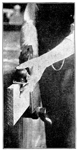
Fig. 52.

Fig. 53.
To remove the portion between the sawed lines take the chisel, Fig. 56 (the same directions to be used for grinding and sharpening a chisel as are used for the plane-iron), pare lightly (about half through the width of the piece), cut down to the gauge line, and then turn the [Pg 44] piece around and finish from the other side, leaving a straight surface at the bottom of the notch. Be careful not to take too heavy a cut, for the chisel will be hard to guide if the workman has to exert his whole strength to push it through the wood. The chisel has a tendency to go down into the work if the flat side is not used as a guiding surface; this side, if kept in contact with the solid wood, will insure a straight surface, and consequently accurate work.

Fig. 54.
[Pg 45]
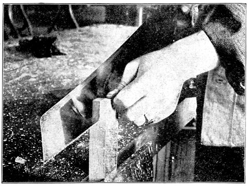
Fig. 55.

Fig. 56.
The lining on the exercise is made with the gauge for the lines running parallel with the edge, with the square and the knife for the lines at right angles to the edge, and with the bevel, Fig. 57, and the knife for the oblique lines. Figs. 58 and 59 give methods for finding the angle of 45 degrees, which is the angle that is used for the oblique lines. [Pg 46]
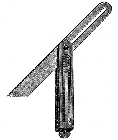
Fig. 57.
Too much attention cannot be given to the operations in this exercise, for in all work that requires material to be prepared, carelessness in detail and inattention to methods, etc., will always appear in the finished work.
Fig. 58.
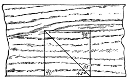
Fig. 59.
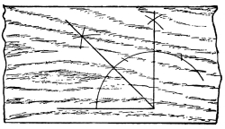
[Pg 47]

Fig. 60.
When two pieces of timber of equal thickness cross each other and the joint is to be flush, i. e., the pieces when joined are to form a flat surface, they are halved together; or, to put it in another way, a piece is taken out of each half its thickness and as broad as the piece [Pg 48] which is to cross it, thus allowing the one to drop into the other, as shown in Fig. 60. The working drawing is shown in Fig. 61.
To make this piece of work, refer to methods and operations given for the preparation of material in the first exercise.

Fig. 61.
Special results are sought for by specific methods in this exercise. Exercises that are not finished (by the methods given) as they should be, are thrown out as not coming up to the requirements and fall short of the object for which they are designed.
The drawing shows two pieces of wood of given dimensions crossing each [Pg 49] other at right angles and halved together, making a flush joint. Requirements: The pieces to be of the exact length, breadth, and thickness called for, fitted closely on both sides, each piece to be exactly in the center of the other, and both sides smoothed off and perfectly flat when finished; the ends of the pieces to be planed square, and the ends of the halving to be fitted from the saw. Methods: After sawing out a piece (long enough to make both pieces, allowing for work on the ends), plane the piece by the methods given for planing in the first exercise; then saw it across in the center and proceed to lay out the pieces so that the face side of each piece will come on the same side; this means that the halving is cut out of the face of one piece and the back of the other (see Fig. 60).

Fig. 62.
It will be well to consider this problem of laying out work as a problem in arithmetic. The pieces called for in the drawing are 5½ inches long, 1½ inches wide, and 1 inch thick. The piece that crosses [Pg 50] comes exactly in the center. Therefore we have a problem like this: 5½″ -1½″ = 4″, which is the difference between the length of one piece and the breadth of the other; but the piece comes in the center, and so we take the difference of the length, which is 4″, and divide it by 2. 4″/2 = 2″, which will give the distance from the end up to the first edge of the cross-piece. As all measurements have a beginning somewhere, we mark a line near the end of the piece as shown in Fig. 62, and from this line we lay off the distance to the cross-piece, marking with a knife point the position of the edge. Then we lay off the width of the cross-piece, which is 1½″, leaving the distance to the other end 2″, the same as at the first end.

Fig. 63.
Having found the position of the edges of the cross-piece, we mark a line across the work (using a knife and a square); then mark the lines down the edges. Now taking the gauge, we gauge from the face side of each piece the depth required. Then we cut a notch inside the lines with a knife, as shown at Fig. 53, place the piece [Pg 51] on the bench hook, saw down to the gauge lines with the back-saw (position shown in Fig. 54), and remove the portions to be taken out by the methods given for the notch in the first exercise.
Then plane the ends of each piece perfectly square to the face side and face edge.
An exercise that was made by a careful student and one that was made by a careless student are shown at Fig. 63, revealing the final results of careful as against careless work.
Having cut out the center pieces and finished the ends we fit them together, seeing that the surfaces come flush; then smooth off the surfaces, being careful not to cut too much off the ends, for this will round the surfaces and thus spoil the work. Sharp tools are essential to good work.
Lines drawn in their proper places, and then cut to, will give the results sought for in fitting.
When beams or pieces of wood stand square with each other, and the strains are also square with the pieces and in the plane of the frame, the most common junction is the mortise and tenon.
A mortise is an opening, which may be square or oblong, intended to receive the tenon, and which may go into the work only a short distance, or may go all the way through. Where it goes only part way [Pg 52] through it is called a blind mortise, and where it passes all the way through, a through mortise. A tenon is a projection on the end of a piece and fits into the mortise. The tenon usually has two shoulders formed by cutting away the sides, and should be about one third the thickness of the piece.

Fig. 64.
There are a number of different styles of this joint and methods of fastening, which we will consider later in our work.
The working drawing shown in Fig. 64 gives the dimensions of the pieces, the material of which is to be worked out in one piece, as [Pg 53] directed in the previous exercise, and then cut up into lengths suitable for the exercise. The student should commence work on a piece with a full understanding of what is required to be done in order to finish the work as called for, and not try to make any kind of work do in order to proceed to the next task.
Notice what is required in this exercise:
1st. That the pieces be perfectly straight and square.
2nd. That the tenon piece be exactly in the center of the mortise piece, and that the angles be right angles or “square.”
3rd. That the work be laid out systematically, with the lines in their proper places.
4th. That the tenon be made altogether with the saw.
5th. That the mortise be cut out with the hand mortising chisel.
6th. That the tenon fit into the mortise, and not be squeezed.
7th. That the joint fit closely, and that the work be finished off smoothly on the sides, with all the corners sharp and the end of the pieces sawed square.
The following methods if carried out will help the student to finish the work as required.
It will be unnecessary to repeat hereafter the method of planing, as the student by this time should have learned to plane the pieces properly to dimensions.
After the material has been planed, mark the piece to the desired lengths as shown in Fig. 65, and saw off the pieces square on the ends. Use the knife to mark the lines. In sawing, care must be taken to saw [Pg 54] on the right side of the line, for the saw will cut out its own thickness and reduce the length of the piece that much if the piece is sawed on the wrong side of the line.
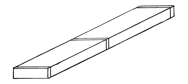
Fig. 65.
Leave the tenon piece about ⅛ inch longer than the drawing calls for so that the tenon will protrude through and be finished off even with the mortise piece.
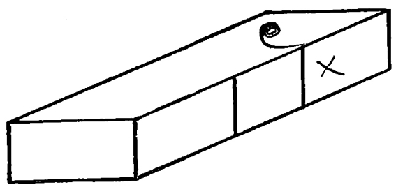
Fig. 66.
Proceed to lay out the work. Take the mortise piece, which is 6 inches long, and mark the distance from one end (6″-1½″ = 4½″.) 4½″ / 2 = ⁹/₂ × ½ = ⁹/₄ or 2¼″; locate the first point on the face edge; then measure from this point the width of the tenon piece, which is 1½″. Through the points just found draw the lines square to the face side. Place the square against the face edge and mark (on the opposite edge on the corner), a small cut for both lines (see Fig. 66) and square from the face side across the edge; lay the piece aside; take the tenon piece and point off the distance from the end of the piece to the shoulder, [Pg 55] and mark across the face and back, using the square and the knife in marking. Prepare the shoulder lines for the back-saw, as shown in Fig. 53, taking care that the notch is cut on the right side of the line.
Take the gauge and set it to the distance from the face side to the first side of the mortise, and gauge the lines for the mortise on both edges; gauge the lines for the tenon. (This is for a single gauge.) Take the mortise chisel, Fig. 67, and make a mark from this line (see Fig. 68), which will give the thickness of the tenon and the width of the mortise; set the gauge out to the width and gauge the rest of the lines.

Fig. 67.

Fig. 68.
Take the rip-saw and saw down the outside of the lines on the tenon piece the length required; cut off the sides with the back-saw. In sawing split the line so that the tenon will be as thick as the mortise is wide. This means that half the line is to be left on the work. Fasten the mortise piece in the vise, putting a piece below to keep it from going down when cutting.
Place the mortise chisel about the center of the mortise; hold it vertically, and with the mallet drive the chisel down into the work; release the chisel and make a new cut, keeping the flat side of the chisel towards the end to which the mortise is being cut. Fig. 69 shows how the cutting should be done. [Pg 56]
Having reached the end, turn the chisel around, and cut towards the other end in the same manner. (Where the mortise goes through it will be unnecessary to take the chips from the first side.)
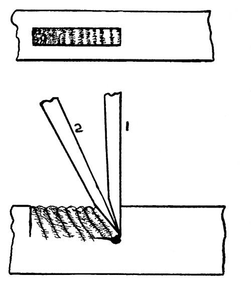
Fig. 69.

Fig. 70.
Turn the piece over, and repeat the operation on the other side, when the chips can be easily removed. Proceed to test the work; see that the mortise is straight on the ends. Generally the student will leave the ends rounding as shown in Fig. 70; this, if the tenon is driven into the mortise, will squeeze the edges out of true (Fig. 71) and leave an opening on the ends of the mortise, as shown in Fig. 72.
Fig. 71.
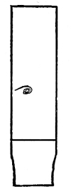
Fig. 72.

Care should be taken to avoid this fault in this exercise. (A mortise gauge such as a joiner uses is shown in Fig. 73; it has two spurs, one being adjusted by the thumb screw at the end of the shank. We will use a mortise gauge in our work later on.) [Pg 57]

Fig. 73.
After the pieces have been cut, put them together, having the face sides together, and finish smoothly.
This method of joining timbers is sometimes used in heavy frame work, but can be used to advantage in light frame work that has to be taken apart, such as curtain frames, etc.
In Fig. 74 is shown the assembled and the detailed drawings of this piece of work. The experience gained from the previous exercises can be used to advantage in working this problem.
The requirements in this exercise are that all pieces be square and to dimensions.
That the upright and cross-pieces when keyed be square to each other.
That the brace fit snugly, and form two angles of 45 degrees back at its junction with the upright and cross-piece.
That all joints fit closely, and the whole work be smoothed off and made true. [Pg 58]
The method of laying out the keyed joint is somewhat similar to that in the third exercise.

Fig. 74.
On the upright locate the cross-piece (on the face edge), which is 1½ inches from the end to the upper edge, and measure the width of the piece, which is 1½ inches; draw the lines square to the face side, deduct the amount of splay or bevel that is given to the mortise and tenon from the lower end of the mortise, and add to the upper end the width of the key; draw the lines, and mark them in some manner so that [Pg 59] they will be known as working lines. Figs. 75 and 76 will show how this may be done.
From the line which locates the lower edge of the cross-piece (using the square on the face edge) mark the position (on the opposite corner) of the lower line on the outside edge, by the method given in the previous exercise (see Fig. 66), and square this line across the outside edge; then measure the width of the tenon, plus the width of the key, and square the line across.

Fig. 75.

Fig. 76.
(Where work is to be finished on the faces, care should be taken not to mark the work with knife lines, but if auxiliary lines must be used, then mark them with a pencil so that they may be cleaned off when the work is being smoothed.)
Having laid out the keyed mortise lay out the brace mortise, the lower end of which is located 3½ inches below the lower edge of the cross piece; the drawing gives all the dimensions for this.
Take the cross-piece and lay out the tenon in the same way that the tenon in Exercise Number 3 is prepared, using the dimensions that are given in the drawing for the work on hand.
After marking the shoulders of the cross-piece lay out the brace [Pg 60] mortise, which is 3½ inches from the shoulder to the farthest end, and mark the other lines as called for in the drawing. Use the single gauge as directed in Exercise Number 3 to mark the side lines of the mortise and tenon, and cut the mortise with the mortising chisel, taking care to cut the ends to the proper angle.
Saw the tenon as previously directed, and after the sides have been cut off, mark the splay on the lower side of the tenon and cut it off with a paring chisel.
The method of finding the length of the brace is of importance, as it will give the student some idea of the application of square root to practical work of this kind.
The hypotenuse of a right-angled triangle equals the square root of the sum of the squares of its sides. For example, take the triangle that is formed by the upright, the cross-piece, and the outside of the brace. We have a triangle that has two sides of equal length and wish to obtain the length of the brace on its longest side.
We will designate the angle where the cross-piece meets the upright, A, and the lower point of the brace on the upright, B, and the outside point of the brace on the cross-piece, C. Then we have the side AB, and the side AC, which we will square and add together, then extract the square root of this sum, which will give us the length of the brace on the longest side, to which we must add the length of the tenons that go into the upright and the cross-piece. The angles at each end of the brace will be 45 degrees, as the opposite angles of the triangle are [Pg 61] equal, there being 180 degrees in the sum of the three angles; one of the angles is a right angle (90 degrees), which we subtract from 180 degrees; the remainder divided by two will give the number of degrees contained in the angle at the ends of the brace.
The lines at the outside of the tenons on the brace are parallel with the upright and the cross-piece respectively.
A method often used by practical men to get the length of short braces is to take a steel framing square and a rule, and find the length of the brace by applying the rule to the square as shown in Fig. 77. On the short leg of the square will be found a brace measure which gives the length of the sides of the triangle and the length of the brace, thus, ⁵⁴″ / ₅₄″ = 76.31″.

Fig. 77.
Bevels and tapers are found by applying the bevel to the square according to the bevel or the taper required, such as 1 inch on one [Pg 62] side and 4 inches on the other side of the square; this would be called a taper of 1 inch in 4 inches.
Having cut the pieces to dimensions as called for in the drawing, put them together, and finish smooth.
Moldings and beads are sometimes used to ornament work, but the chief use of the bead is to conceal open joints by the shadow it casts. An example of this may be seen in beaded wainscoting or large surfaces that are finished with matched ceiling. If the boards were put together without a beaded edge, an unsightly crack would be the result from the shrinking and swelling of the material.
Moldings are so varied in form that it would be useless to try to describe them here. The molding shown in the drawing is given for practice in the use of the molding plane.

Fig. 78.
A rabbet is generally a square corner cut out of the edge of a piece so as to lap over, or to make a place for glass, etc., as in window sash, glass panel doors, and door frames. The rabbet plane (see Fig. 78) is so constructed that the iron comes out flush with both sides, so that it will cut out a sharp corner or interior angle. [Pg 63]
To cut the rabbet, the iron combination plow, beading, and rabbeting plane may be used, an illustration of which is shown in Fig. 79.
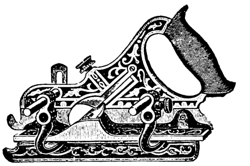
Fig. 79.
This tool can be set up as a rabbet plane or fillister, having a fence to guide it along the side and a shoe to stop its cutting when the desired depth is reached.
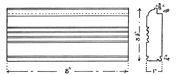
The plan and end elevation of this exercise is found in Fig. 80. The bead plane, Fig. 81, that is used on the edge of the exercise is known as a single quirked bead, and has a fence or guide by which it is held in position while the bead is being stuck on the work.
Fig. 80.
The angle bead is made with the same plane, but the work must be turned in order to cut the quirk on the other side. [Pg 64]
The center bead plane (see Fig. 82) is a double quirked bead plane, and requires a piece fastened on the work in order to guide it.
Fig. 81.
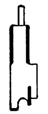
Fig. 82.
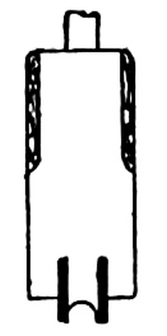
The guide piece can be held in place by several methods; one method is to tack it on to the work, but this leaves the nail holes in the work. Another method is to make a piece as shown in Fig. 83; if the work is long a thin strip with small blocks fastened on the ends, Fig. 84, and a wedge driven between one of the blocks and the work will hold it firmly in place.
Fig. 83.

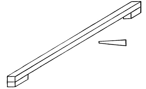
Fig. 84.
After planing the piece to the desired dimensions we would advise the student to follow the following order of work:
First, cut the rabbet.
Second, stick the center bead and cluster of beads or reeding.
The reeding is done by first sticking one of the beads by means of the guide piece and then letting one of the quirks of the bead plane follow in the quirk of the bead already stuck.
Third, cut the edge and angle beads. [Pg 65]
Fourth, stick the molding.
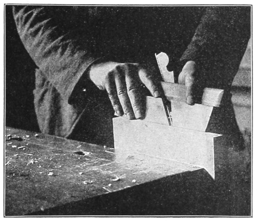
Fig. 85.
In Fig. 85 is shown the molding plane held in position for work. On the front end of the plane will be found a line, which must be kept vertical when the plane is at work. Finish the beads with sand paper in order to remove all roughness.
Bead and molding plane irons are ground on an emery wheel with a rounded edge.
The sharpening is done with a slip-stone. A slip-stone used for beads and molding planes is wedge-shaped in the cross section, with rounded edges (see Fig. 86).

Fig. 86.
Where sharp corners occur in molding plane irons, triangular and square slips are used.
[Pg 66]
It has already been mentioned that a bead is used in decoration. An application of the bead as a decoration is given in connection with the use of the rabbet in this exercise, the bead can be applied to door frames where glass panels, etc., are to be used.

Fig. 87.
In Fig. 87 is shown the working drawing. The features in this exercise to be specially noticed are the method of joining the bead so as to form a continuous bead around the edge, the method of laying out and [Pg 67] cutting the shoulder so that the opening in the frame will be kept to size; the mortise and tenon used here is what is called a blind mortise and tenon.
Having noticed these features, proceed to prepare the material, by methods previously given, to dimensions called for in the drawing. The requirements for this exercise are that all measurements be correct, that all joints fit closely, that the angles be right angles, and that the work be finished in a neat workmanlike manner.
The material having been prepared, proceed to lay the work out.
Suppose this exercise to be the top of a glass panel door; the pieces on the sides of a door are called the stiles; the cross-pieces are called the rails, and, according to the position they occupy, are called respectively the top rail, the mid-rail, and the bottom rail. The pieces that stand in the center are known as muntings.
To lay out the work, mark out the mortise on the top of the stile about 1½ inches from the end. It will be noticed that the mortise is not so long as the top rail is wide; the piece that is cut out of the tenon is known as a rebate or rabbet. The reason for cutting out this piece and shortening the mortise is to strengthen the joint by leaving a piece of solid wood so that the mortise will not be open on the end. Fig. 88 shows the piece marked out for the stile; the arrow heads in the figure are known as witness marks and show between what lines the cutting is to be done.

Fig. 88.
[Pg 68] The shoulders on the top rail and on the muntings are to be specially noticed. In laying out the top rail the opening between the munting and the stile is 4 inches. The shoulder on the face side of the top rail reaches to the farthest side of the bead so as to form a close fitting joint, and the shoulder on the back reaches to the bottom of the glass rabbet.
In order to keep the opening as called for in the drawing and to miter the bead so as to make it continuous around the edge, lay out the work in the following manner: Locate a line on the edge of the rail that will represent the side of the opening next to the stile, leaving enough for the tenon; then lay off the width of the opening; draw a line which will represent the end of the mortise for the munting; mark the length of the munting mortise. On the inside of each end of the mortise lay off the width of the bead which is stuck on the munting.
Return to the first line which represents the opening, and add to the outside of that the width of the bead and rabbet; then from those lines mark across the face from the line which will represent the bead, and across the back from the line which represents the depth of the glass rabbet.

Fig. 89.
Prepare the shoulder lines for the saw as directed in previous work. The lines to be drawn on the edge of the rail are shown in Fig. 89.
The shoulders on the munting are prepared in the same way as the rail. [Pg 69] In marking the sides of the mortise and tenon use the mortise gauge (see Fig. 73).
Cut the mortise and the tenon as directed in previous work, using a narrow chisel to remove the chips from the mortise. The bead is to be joined so that it will appear continuous; the method of joining is called mitering. A miter is made by cutting, at an angle of 45 degrees, the pieces to be joined.
The practical man will try many methods of cutting material in order to save time. For instance, if he is to make frames where the corners are to be mitered, he will make a miter box. This box (which is not a box at all) is three pieces fastened together to form a bottom and two sides, all of which must be true before being nailed together; then by cutting across the sides in both directions with the saw at an angle of 45 degrees and square to the bottom, the so-called miter box is made, an illustration of which is shown in Fig. 90. Iron miter boxes are now in general use; of these Fig. 91 is a good representation.

Fig. 90.
In the mitering of the bead, a templet, which can be made by the student, is of great service. [Pg 70]
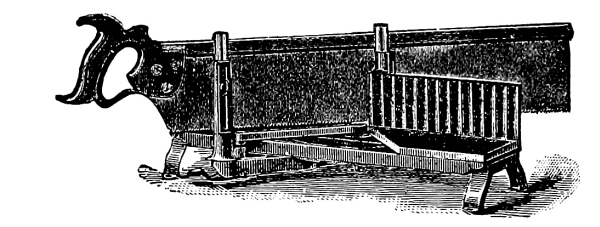
Fig. 91.
A templet is a mould or pattern used as an auxiliary. The templet for this work is made in the following manner. Take a piece and rabbet out one corner as shown in Fig. 92; then cut the ends as shown in Fig. 93, which are at 45 degrees. With this templet placed on the work as shown in Fig. 94, with a chisel cut off the bead, which protrudes beyond the templet.
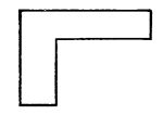
Fig. 92.

Fig. 93.

Fig. 94.

Fig. 95.
[Pg 71] At the mortises remove part of the bead as shown in Fig. 95; then place the templet in position, and cut to the angle.
Care should be taken to see that the mortises are cut square to the edges on the ends, so that they will not squeeze the tenon when putting the work together.
After all cutting and fitting is done glue the work (see note on glue at the end of the book), and clamp the pieces together with handscrews. Handscrews are of the form as shown in Fig. 96.

Fig. 96.
In order further to strengthen this kind of joint, small iron pins may be driven into the back through the tenon, but they must not come through the work. The pins may be made by cutting wire brads off to the required length and driving them in and setting them below the surface with a nail set. After the glue is set finish off the work with a smooth plane.
One of the most important methods employed by the joiner is that termed dovetailing, which is of three kinds, namely, common, lap, and miter. Common dovetailing (see Fig. 97) shows the form of the pins or projecting parts, as well as the excavations made to receive them. Lap [Pg 72] dovetailing is similar to this, but in that system the ends of the dovetails of the side A, Fig. 98, are shortened, and the recesses which are to receive them in B are not cut through when joined together; only the ledge is visible on the return side.

Fig. 97.
[Pg 73]

Fig. 98.
[Pg 74]
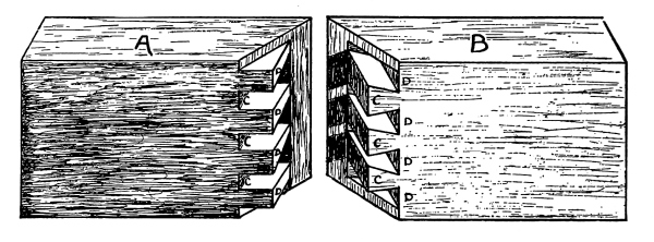
Fig. 99.
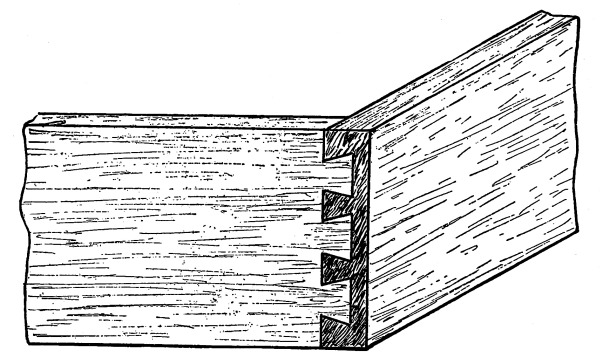
Fig. 100.
Miter dovetailing (sometimes also called secret dovetailing) conceals the dovetails, and shows only the miter at the edges. The manner in which this joint is made will be understood from Fig. 99, in which the two parts A and B are given, each part being lettered to correspond with the position it is to occupy when the sides are joined. Concealed dovetailing is particularly useful where the faces of the boards are intended to form a salient angle; that is, one which is on the outside of any piece of work; but when the faces form a re-entrant angle, that is, a joint to be seen from the inside, common dovetailing will answer best; for, first, it is stronger, because the dovetails pass entirely instead of only partly through; secondly, it is cheaper, for the dovetails which go through the whole wood take up much less time in [Pg 75] working than where a miter has to be left; and further, if well executed, the dovetails are, by the very nature of the work, concealed internally.
Fig. 100 shows a variation of the common dovetail, used in attaching the fronts of drawers to the sides, and for similar purposes.

Fig. 101.
In Fig. 101 is given the working drawing of the common dovetail, and Fig. 102, A-B shows the details of each piece. [Pg 76]
The stock can be prepared in one piece (having it long enough so that if a poor joining is made, the dovetails can be cut off and new ones cut on this piece). After planing, cut in two, square one end of each piece (the ends to be joined). To lay out the work, it is advisable to lay out the piece with the pins or tenons first. From the squared end measure in the thickness of the side; then mark on both sides, using the knife to draw the lines.

Fig. 102.
On the face side (which is the side that would be toward the inside of a box) lay off the lines shown for the pins in the detail marked A, Fig. 102. These lines can be drawn from the working edge with a gauge, or, if the ends are perfectly square, the square can be used (the lines being parallel with the edge). From these lines will be drawn the oblique lines across the end with the bevel set at a taper of 1 inch to 4 inches. The bevel can be set by the steel framing square, by the methods already given.
After drawing the lines saw down the required depth on the outside of the line, and remove the pieces between the pins or tenons by first [Pg 77] boring a hole through the piece to be removed, then cutting from both sides with the chisel.
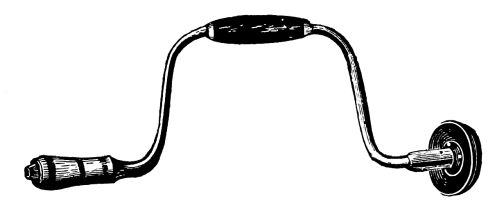
Fig. 103.

Fig. 104.
(The boring is done with the brace, Fig. 103, and the bit, Fig. 104. Bits are of different forms; Fig. 105 shows a number of different styles).
It will be necessary only to draw the lines across the end of the piece marked B, Fig. 102, as the marking of this piece for the recesses will be made by holding in position the piece already cut, and scribing or marking the pins or tenons, then squaring the lines across the end.
Great care must be taken in sawing the mortises if a perfect fit is desired. This can be done only by sawing on the inside of the line, cutting the lines in two. The pieces should go together by light driving, and should be perfectly square on the inside. If the joint is satisfactory take apart and glue together. After the glue is dry the [Pg 78] joint can be smoothed and the ends of the pieces cut off and squared to the proper dimensions given in Fig. 101.

Fig. 105.
[Pg 79]
The preceding exercises are only a few of the methods employed by the workmen in joining pieces together. The experience gained in their execution will be of great help in the work that follows.
Fig. 106 shows the working drawing for a small frame door for a glass panel; the details and sections of the pieces required are shown in Fig. 107.
It must be taken into consideration that this door is actually to fit into an opening of a given size, and a little forethought will be necessary to work the material so that when all cutting and fitting is done the correct size will be the result of the labor expended.
Study the drawing and make out a bill of lumber, noting what work must be done in order to proceed intelligently with the work.
The outside size of the door is 9 inches by 12 inches, and the width of the stiles is 2 inches. The width of the top rail is 1½ inches, and the width of the bottom rail is 2 inches, so that (allowing a little on the length of the rails so that the tenons would project through the stiles about ⅛ inch, and the stiles would project beyond the rails about ½ inch, leaving what is known to workmen as horns) the bill of lumber would be:
| Bill of Lumber |
|
2 pieces | 13 in × | 2 in × | 1 in. |
| 1 piece | 9¼ in × | 2 in × | 1 in. | ||
| 1 piece | 9¼ in × | 1½ in × | 1 in. |
[Pg 80]

Fig. 106.
It must also be taken into consideration that the door must be planed on the edges and the ends when it is all put together; it will be [Pg 81] necessary to allow for this work when the material is being planed; having the stiles and rails a little over size in width will provide for this.
The laying out of this exercise is important, for there are several things to be considered; we must first find out the depth of the rabbet and the width of the molding before we proceed to lay out the work.
It will be seen from section drawing A, Fig. 107, that the molding from the edges of the piece to the quirk is ⁵/₁₆ inch, (this is the depth that the molding plane cuts); the rabbet is also the same depth; the opening between the stiles is 5 inches; to this must be added the depth of the molding and rabbet on both sides, which makes the distance between the shoulders of the rails 5⅝ inches.
A simple rule to follow in laying out work, where pieces are in pairs or right and left, is to place the pieces together with their faces out and their edges up.
Placing the rails in this position, lay out the rails. At the end draw a line across the edges. (It must be remembered that when the pieces were sawed out, they were left a little longer than the width of the door, so that the position of the first line is to be determined by the amount of extra stock left). From this line measure off the width of the door and mark across the other end. From these lines measure in the width of the stiles, which is 2 inches; this gives the width of the opening. [Pg 82]

Fig. 107.
[Pg 83] We saw from A, Fig. 107, that the depth of the molding and the rabbet was ⁵/₁₆ inch; so from the 2 inch line we measure back on each end ⁵/₁₆ inch; this gives the lines from which the shoulder lines are to be drawn across the faces and the backs of the pieces. Prepare shoulders for back-saw as directed in other work.
Now, taking the stiles, and placing them together by the rule given, lay out the lines for the extreme length of the door, and from one end measure in the width of the top rail (1½ inches). From the other end measure in the width of the bottom rail (2 inches). From these lines measure back the length of the mortises. It will be understood that by measuring is meant that lines are to be drawn.
Lines are also needed on the back edges of the stiles for the mortises, as the mortise is cut all the way through. To obtain those lines apply the method given in exercise No. 3; never mark lines across the outside of the work unless it is absolutely necessary, and then with pencil only, so that they may be cleaned off when the work is being finished.
The marking of the sides of the mortises and the tenons is done with the mortise gauge set to the dimensions given in the drawing, the gauge to be applied to the face side. Cut out mortises and tenons as in former work, using the ¼ inch mortising chisel which is found in the tool room.
(All gauging for mortises and tenons having been done from the face side, and all cutting having been done to the lines, it necessarily follows that the face side of the door will be flush. This is absolutely necessary for the molding and the rabbet to match.) Take the [Pg 84] combination plow and set it to cut the rabbet, applying the fence to the face side and cutting the rabbets out of the corners opposite to where the plow is placed. See that the shoe is set to stop the plane cutting when the desired depth is reached.

Fig. 108.
Fig. 108 shows how this may be done. After cutting the rabbet, stick the molding (which in this case is called a Gothic or Scotia molding). Prepare the stiles as shown in Fig. 107, B.
The joining of the molding is to be what is known as coping. This is done in the following manner: The molding is left projecting beyond the inside end of the mortises, as shown in Fig. 107, B. The molding on the rails is to be cut at an angle of 45 degrees. This is done by taking the templet used in Exercise No. 6 and placing it on the rail as shown in Fig. 107, C, and cutting the molding with a chisel down to the [Pg 85] tenons. This will give the line by which the coping is to be cut. The cutting is done by using the gouge, Fig. 109, one that is ground on the inside preferred; cut the coping deep enough to receive the molding which projects beyond the mortise, Fig. 107, B. The line which will show at the joining of the molding on the face of the exercise will look like a miter joint. This joint has the advantage of always being close, for no amount of shrinking or swelling will open it.

Fig. 109.
After all cutting is done, put together and see if all joints fit; having tenons cut as shown in Fig. 107, C. This allows room for wedges.
The wedges are cut with a back-saw out of a piece of board of the same thickness as the tenons. Fig. 110 shows how this is to be done.
If the joints are all satisfactory open them enough to allow the glue brush to go between the shoulders and the stiles; put a little glue on both sides of the tenons and drive together, putting clamps or large handscrews on to bring the joints up close; dip the points of the wedges [Pg 86] in glue and drive them between the ends of the mortise and the edges of the tenon; remove the clamps and let the glue set before smoothing the sides of the work. The door, when the wedges are driven and clamps removed, will look as shown in Fig. 111.
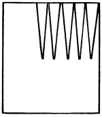
Fig. 110.

Fig. 111.
The ends of the tenons and horns are sawed off and the edges planed. The gouge, (Fig. 109), has a blade that is curved in its section the whole length; gouges are of different sweeps. The bevel which is ground on the cutting edge may be on the concave or the convex side; and according to this grinding the tools are known as inside and outside gouges. The sharpening is done with a slip-stone. [Pg 87]
After the glue is hard enough, smooth the surface with the smooth plane, and then take sand paper and finish the work. Put the sand paper on a block, being careful not to round the surfaces when using it.
(This exercise may be omitted at the option of instructor.)
It will not be necessary to give many directions for this exercise, as the student by this time should have learned the sequence of operations in preparing material. The special points to be noticed in the working out of this exercise are that the sides are cut out with the rip-saw; the ends cut with the back-saw; the sides to be finished with the plane, using the rabbet plane to plane the corners at the stops at the ends, and the jack-plane for the rest of the surfaces. Surfaces are to be finished with sand paper and shellaced.
In Fig. 112 will be seen the working drawing. The thickness of stock required is 1¾ inches. The angle at which to set the bevel for the ends is ½ inch in 4 inches. All the other dimensions are found on the drawing.
After the piece is cut out and finished with sand paper, give it a coat of shellac varnish and let it dry from 8 to 10 hours. Then with No. 00 sand paper smooth the shellac (but do not cut through). After which [Pg 88] give another coat. To obtain a glossy surface the pores of the wood must be filled with the varnish; by repeating the operation with the sand paper and giving another coat of shellac, a very good surface will be obtained.

Fig. 112.
Care must be taken in putting on the shellac varnish not to put it on too thick, as it sets or dries quickly and an uneven coat of varnish is unsightly. Spread it quickly; see that plenty of shellac is on the brush; do not go over it after it has once been spread evenly, as it will roll up in small lumps which will have to be left to dry before anything can be done to it, and then it will take a great amount of labor to smooth it.
This is one method of finishing with shellac varnish.
To prepare shellac varnish see note.
[Pg 89]
There are so many ways in which a box may be made that it would be out of place here to enumerate them all. The joints used here are known as butt joints.
Fig. 113 is the working drawing; the details of the work are shown in Fig. 114.
The first step to be taken in making this exercise is to make out a bill of lumber. By the drawing we find the length of the box to be 12 inches, the width to be 7 inches, and the height to be 5 inches, allowing ⅛ inch on each end of the sides for finishing. The side pieces would be 12¼ inches. The thickness of the sides is ½ inch and the ends are let into the sides ¼ inch as shown in Fig. 114, A; this would make the length of the ends 6½ inches finished; one end being ½ inch narrower than the other to let the top slide over it in the groove on the sides. The width of one end would be 5 inches, and of the other 4½ inches. The bottom is to be let into the sides and ends in a groove which is ¼ inch deep. This would make the bottom 11½ inches long, 6½ inches wide, and ½ inch thick. The top slides in the groove shown in the section at B, Fig. 114, which is ¼ inch deep, and the end of the top goes into the groove in the end of the box, which is ¼ inch deep. This would make the length of the top 11¾ inches, the width 6½ inches, and the thickness ½ inch. The bill of lumber would be as follows:
| Bill of | Sides, | 2 pieces | 12¼ in × | ½ in. | ||
| Lumber | Top, | 1 piece | 11¾ in × | 6½ in × | ½ in. | Finished |
| Cherry | End, | 1 piece | 6½ in × | 5 in × | ½ in. | Size. |
| or Birch | End, | 1 piece | 6½ in × | 4½ in × | ½ in. | |
| Bottom, | 1 piece | 11½ in × | 6½ in × | ½ in. |
[Pg 90]

Fig. 113.
[Pg 91]

Fig. 114.
[Pg 92] The material used in this exercise will be planed nearly to the thickness by the planing machine, enough being left to smooth the work. Select and lay out on a board the pieces required (allowing enough for the work on the edges). Saw out the pieces; then plane the edges by the methods given, omitting the planing of the face side and the back, but select and mark the sides for the working faces.
The extremities of the end pieces are to be planed perfectly square to insure a close fit against the sides. The method of planing the ends is to plane half way through from the edge, then plane from the other edge, being careful not to let the plane go all the way across, as the corner will be liable to break off.
It will not be necessary to plane the ends of the sides until the box is glued together, when they can be finished off even with the end.
To lay out and prepare the sides, place the pieces together, faces out and edges up, draw a line across the edges at the ends for the full length of the box, then measure back the thickness of the ends. From these lines mark across the faces of each piece. It will be noticed that one end of each side can be sawed across, but the other end where the top enters the grooves will have to be cut partly with a saw and the rest of the way with a chisel. Prepare the ends the same as the shoulders of the tenon, being careful not to cut the groove all the way across where the top enters.
Gauge the depth to which the ends go into the sides, and after sawing [Pg 93] across remove the pieces from the corners with a chisel. It will be necessary only to have the end pieces the correct length, as there will be no lines to be drawn on them.
Take the plow plane and put a ¼ inch iron into it, and set it for the grooves that are cut out of the sides and the ends.
The grooves are all the same distance in from the edges and are all the same depth. To protect the bench while using the plow, get a piece of board and on it fasten pieces to hold the work while running the groove. This is done by sawing out three or four pieces as shown in Fig. 115, and fastening them to the board as shown in Fig. 116.
Fig. 115.
Fig. 116.

Fig. 117.
The tongue on the edges of the top and the bottom can be made with the plow by fastening the pieces in the vise and rabbeting out the corners as shown in C, Fig. 114.
After all cutting and fitting has been done smooth the inside of each piece with the plane; then take the steel scraper (shown in Fig. 117), and scrape the surfaces; then finish with sand paper; glue the corners; put the bottom in place and fasten together with hand screws and let dry. There are no nails used in the construction of this exercise. [Pg 94]
Finish the outside of the box in the same way that the inside was done.
After finishing the outside and the top, use filler or stain to color the wood. The filler is a mixture of fine whiting and linseed oil with a little turpentine to act as a dryer, colored with any of the pigments desired. A little experience is necessary in using the colors to obtain the desired shade.
The filler comes already prepared, of a cream color, and must be colored as required. Apply the filler with a brush, and let it stand on the wood for a short time; then rub it off with cotton waste or a rag; then set the work aside until the surfaces are perfectly hard; then give a coat of shellac varnish and let it dry. Repeat the operation two or three times, using sand paper to smooth each coat of varnish.
After the varnish is thoroughly hard, take powdered pumice and oil or water, using a soft rag, and rub the surfaces until they are smooth; then take rotten stone and oil and rub until it has a fairly bright gloss. Rub with a soft dry cloth, then finish with the palm of the hand until a bright glossy surface is obtained.
For polishing see note.
The preceding work is what might be termed joiner work; the carpenter also is called upon to join timbers, and uses to a great extent the same joints that the joiner does, but the joiner’s work is usually where it must bear inspection, whereas the carpenter’s work is generally [Pg 95] covered over either by plaster or casings. A single mechanic may be able to perform every kind of work that is required in the construction of a building; thus the two trades are usually spoken of as one, i. e., carpenter work.

Fig. 118.
In Fig. 118 is shown a method that is sometimes used in the construction of trusses. A truss is that part of a roof which supports the purlines, rafters and sheathing. A roof is the covering or upper enclosure of a building with the frame work by which it is supported. It may be of almost any shape. A light roof is usually of moderate span, without trusses, the rafters being supported by the walls or partitions of the building. A heavy roof is employed for wider spans, [Pg 96] and the rafters are then supported by the purlines and trusses. A truss is usually required for spans of more than 20 feet.[A]
The span of a roof is the horizontal distance between the external surfaces of the walls of the building; its rise is a vertical let fall from its ridge to a horizontal line joining the intersections of the external surfaces of the walls and the roof surfaces. The inclination of a roof equals the angles between its surface and a horizontal.
The span of a truss is the horizontal distance between the centers of its end joints, and is usually the same as that between the centers of the walls, which support the truss. Its rise is the vertical connecting its span line and the center of the joint at the apex or highest point of the truss.
A member of a truss is any straight or curved piece which connects two adjacent joints of the truss.
The upper chord is composed of the members which form the upper edge or margin of the truss. Each half of the upper chord of a triangular truss is often called a principal. The lower chord is composed of the members forming the lower edge of the truss. If straight, this is termed the tie-beam or tie-rod; the first being a wooden timber; the second, one or more rods of iron.
The web members connect the joints of one chord with those of the other, and may be radials in case of curved trusses, diagonals, or verticals. They are commonly called struts where they resist [Pg 97] compression, ties where they resist tension, and strut-ties where they resist compression and tension.
A joint is the connection of two or more members whose center lines must intersect at a common point if possible, this common point being the center of the joint.
The rafters of light roofs are not trussed, but rest directly on the walls, and support the sheathing and covering of the roof.
Heavy roofs are supported by trusses resting on the side walls.
The sheathing is supported by rafters which rest on the purlines, these being supported by the trusses.
The drawing, Fig. 118, shows the half of a truss; the members are the upper chord, the lower chord, and a strut.
Although carpenter work is usually of a rough character, the joints of a truss should fit snugly so that there will be no room to give when loaded; so, for the practice, the student will plane the stock either to the sizes given in the drawing or double the sizes, making the whole truss as time and circumstances permit. (This to be determined by the instructor.) [Pg 98]

Fig. 119.
Fig. 119 shows what is termed a truss diagram; the distance from point A, to B, is the distance between the center of the walls, and the angle A, C, D, is the inclination or pitch of the roof. The pitch of the roof is determined by the distance the peak of the roof rises above the walls; thus if a roof has a quarter pitch, the peak would rise above the walls one quarter the width of the building; if half pitch the peak would rise one half the width of the building, etc. For simplicity in laying out this problem we will make the pitch one half. The points A, B, represent the span of the walls; also the lines A, C, and B, C, show the outside margin of the upper chord of the truss. By bisecting A, B, and erecting a perpendicular at D, to C, we divide, the triangle A, B, C, into two triangles, A, D, C, and B, D, C. Now, the line A, C, is the hypotenuse of the right-angled triangle A, D, C. We had one example of finding the length of the hypotenuse of a right-angled triangle in Exercise No. 4. The workman who lays out rafters or trusses rarely takes time to calculate the hypotenuse of the triangle, but uses the steel framing square in the following manner. He obtains the horizontal distance at the bottom of the rafters, and the pitch. Take for example a truss that is 30 feet across from point to point, and a [Pg 99] pitch of one half; then the distance the peak would rise would be 15 feet. Take the framing square and lay it on the chord, taking 12 inches on the blade and 12 inches on the tongue and mark off 15 triangles as shown in Fig. 120, which is half the width of the building. The rise was also 15 feet; so by using the square as shown, we obtain the rise and the run of the rafter. The line on one side of the square gives the angle at which the chord or rafter is to be cut at the peak. The line at the other end of the chord gives the line from which to measure the distance the tenon and shoulders go down into the tie-beam. The strut shown in the drawing, Fig. 118, has one joint square, and the other at an angle of 45 degrees. Where the pitch is one half, the angles are 45 degrees and right angles.

Fig. 120.
[Pg 100] The line E, D, on the diagram represents a tie-rod, which by the construction of this truss would naturally tend to stiffen the structure by supporting the center of the tie-beam.
Wire, nuts, and washers are supplied (where the student makes a whole model) to make the tie-strut.
The student in writing out notes will make two sketches of trusses he may have observed on shop visits. The buildings visited almost all have trussed roofs, either wood or iron.
[A] Definitions from Ricker’s Trussed Roofs.
Two or three students may work together on this problem.
Read all through before commencing work.
The stair and the hand-rail may be considered as one problem, since the hand-rail forms part of the completed staircase, but they are separated into two distinct problems for convenience in working them out.
In Fig. 121, is shown the plan and the elevation of the stair, the dimensions for each piece required are calculated by the student from this drawing. The name of each piece also is found in Fig. 121. The nosing is to be added to the width of the tread. The nosing is the part which projects beyond the front of the riser.
The thickness of the stringers is to be ½ inch, the risers ⅜ inches, the treads ⅜ inches, and the well-hole is to be built up as in practical work, as shown in Fig. 122. [Pg 101]
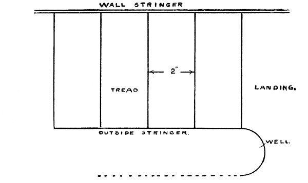
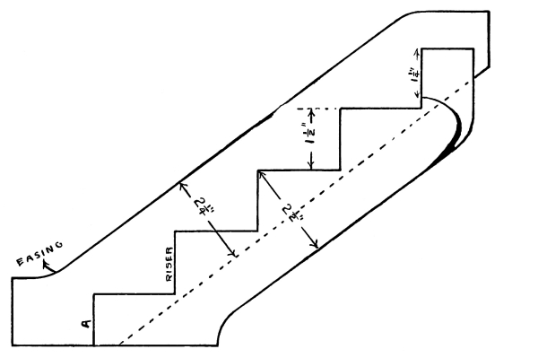
Fig. 121.
| Length | Width | Thickness | |
|---|---|---|---|
| Wall stringer | “ | “ | “ |
| Outside stringer | “ | “ | “ |
| Risers (5 pieces) | “ | “ | “ |
| Treads plus nosings (4 pieces) | “ | “ | “ |
| Top tread (1 piece) | “ | “ | “ |
| Well-hole piece | “ | “ | “ |
[Pg 102]
Fig. 122.

[Pg 103] After the material is prepared, proceed to make the templets. The templets required are shown in Fig. 122.
Templet E, is used to lay out the brackets for the risers and treads on the wall and outside stringers; templet G, to lay out the housing for the treads on the wall stringer; templet H, for the housing for the risers on the wall stringer.
Now take the piece for the wall stringer, A, Fig. 122, and draw the line X, Y; proceed to lay it out.
Commencing at the bottom, lay templet E on the piece as shown at 1 A, and draw lines for the riser and the bottom of the tread; then place the templet as shown by 2 A, (remembering that in order to have the bottom step the same height as the others the bottom riser must be the thickness of the tread narrower than the others. This will be seen by looking at the drawing, Fig. 122, which shows the height of the risers). Then place templet E, in position as indicated by 3 A, and draw the line for the riser and the tread, and so on until all the lines have been drawn which will represent the front of the risers and the bottom side of the treads.
After having drawn these lines, take templet G, and place it on the tread line as shown at J, Fig. 122, and draw the lines for the top of the steps, the nosing, and the wedges; the thickness of the step is to be measured up from the tread line.
Now take templet H, place it in position on the riser lines, J, Fig. 122, draw lines back of the riser line for the thickness of the risers [Pg 104] and the wedges; then proceed to cut out the housing in the following manner:
Take a center or auger bit the same size as the thickness of the step and bore the depth that the housing is to be, as shown at 5 A, Fig. 122; then take a chisel and cut out as shown at 4 A, Fig. 122. This will give room to use the back-saw to cut the rest of the lines. Now take a chisel and remove the pieces to the depth required, which, in this case, is ¼ inch; cut for the risers and remove in the same manner.
In larger work of this kind a router should be used.
To lay out the outside stringer take templet E, Fig. 122, and mark as at B, Fig. 122. The riser is to form a miter with the front of the bracket; so it will be necessary to begin at the top step and saw the stringer off square to the face; then take a bevel (which will be set at an angle of 45 degrees) and mark from the riser line so that it will form a miter. Saw down this line; then saw the next tread line square to the face. Repeat with the bevel as before, and saw the next riser line, and so on until the bottom is reached. C, and D, Fig. 122, show how the risers and the treads are to be cut. The ends of the risers are to be cut at an angle of 45 degrees to fit the bracket on the outside stringer. The end of the step is cut as shown in order to receive the return nosing. The dovetails on the end are to receive the baluster which supports the hand-rail.
The piece F, which is to form the well-hole, is built up of pieces, then planed out with a round bottom plane. The method of fastening this piece to the stringer is to halve the stringer and to cut out the [Pg 105] well-hole piece to receive it; then glue and screw together.
I, Fig. 122, shows what the top or landing step is to be.
The curves that are shown at the bottom and the top of the stringers are known as easings. The student will use his own ingenuity in forming the easing, remembering that a little glue will fasten pieces together, and that it is not necessary to take a board the whole width at those points of the stringers to accomplish this.
To put the stairs together after all the pieces have been prepared, place the bottom riser in place and fasten it in with glue and a wedge; then toe-nail it into the stringer from the back. Now fasten the outside stringer to the riser, bracing it into position; then fit the second riser and the first tread into place; then fasten with glue and wedges, and toe-nail the riser and the tread to the stringer. The treads will be nailed to the risers so as to unite the work firmly together.
Another method of fastening the riser to the tread is to groove the front edge of the tread and have a tongue on the riser, an illustration of which is shown in Fig. 123.

Fig. 123.
To decorate stairways mouldings are used; generally a cove moulding is fastened under the front and the end of the tread, an illustration of [Pg 106] which is shown at Fig. 124. The hammer is used in this problem; it is hardly necessary to explain its use.
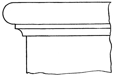
Fig. 124.
Toe-nailing is the driving of nails obliquely in order to fasten two pieces that may be at an angle to each other, as illustrated by Fig. 125.
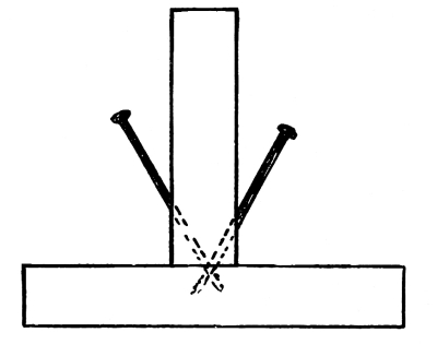
Fig. 125.
The student, not having had wood turning as yet, will not consider the making of the turned balusters, such work being introduced in the course in wood turning.
In commencing work on the hand railing, notice the several parts that [Pg 107] have to be made; first, the newel post; second, the easing at the bottom of the stairs; third, the straight piece of railing; fourth, the return or twist at the top.

Fig. 126.
Fig. 126 shows the working drawing for the newel post, the explanation of which will be unnecessary. The easing is the bend in the rail before it strikes the newel post. The method of laying out a graceful easing is shown in Fig. 127. The straight piece of rail is worked out with the hollow and the round planes which are to be found in the tool room.
The return or twist requires to be developed by descriptive geometry, and to do this we will refer to drawing Fig. 121 in order to find the diameter of the well. It will be noticed that one half of the twist is parallel with the landing and that the curve for that half would be a true quarter circle, while the other half of the twist, that part which follows the incline of the stairs, would be part of an ellipse. [Pg 108]
To demonstrate this, take a cylinder and cut it at an angle to its axis; the section through which the cylinder was cut would be an ellipse, an illustration of which is shown by Fig. 128. To develop this part of the ellipse lay out, on a board, by the following method, a full sized drawing of the rail required.

Fig. 127.
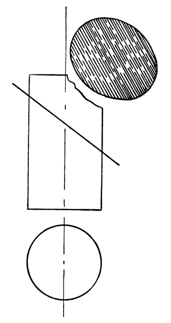
Fig. 128.
On the board draw a straight line which will be the center line of the well, and on any convenient point placing the leg of the compass (which will be set at the required radius), describe a semi-circle, which will represent the diameter of the well given in the plan in Fig. 121. Now from the semi-circle draw lines parallel to the center line, which will represent the outside stringer of the stair and the casing on the landing. Fig. 129 shows the development thus far. [Pg 109]
The rail is to be 1¼ inches wide and the balusters to be ½ inch square. The side of the balusters which come on the outside of the stairs comes even with the stringer, and the rail is to be placed so that the balusters are on its center.
From the line which is already drawn to show the part which is parallel to the landing, draw a line for the center of the rail, and on each side of the center line lay out half the width of the rail. On the other half, which represents the outside stringer (the incline of the twist), draw the center line of the rail for the straight part; then draw lines for the width of the rail as on the other half. Now, to obtain that part of the ellipse required, take the pitch-board E, Fig. 122, and place it on the drawing as shown in Fig. 130; then draw lines from points X, Y, Z, perpendicular to the center line. Now set the compass to the distance A, B, and mark the distance A, B, on each side of the point Y. This gives the width of the piece required for the twist on the center line.

Fig. 129.
Describe the ellipse. The major chord would be 2 (E, F,) for the outside ellipse, and the minor chord is G, H, for the inside. [Pg 110]
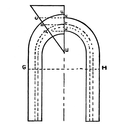
Fig. 130.
There are several methods used in describing an ellipse which the student no doubt has used in studying geometry, but the practical stair builder uses a trammel and block. The block is grooved through its center as shown in Fig. 131, and the trammel is a strip of wood; a pencil is fastened on one end and pins are fixed at points to be found by trial near the middle. Fig. 132 shows how the trammel is made. The pins slide in the grooves of the block, and the pencil marks the curve required.
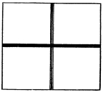
Fig. 131.

Fig. 132.
[Pg 111]

Fig. 133.
[Pg 112] Fig. 133 gives a very comprehensive idea of the pieces before they are worked down. The pieces at the right and at the top are the moulds, and the mould for the rail is on the top of the piece which is seen in the front of the figure.
After having laid out the lines as directed make the moulds or templets out of thin stuff; then mark the stock (out of which the pieces of the rail are to be made), by the templets, and saw them out, either with a compass saw, or with the band-saw where it is convenient to do so.
It will be noticed that the piece out of which the curved or twisted piece is made is thicker than the piece which is parallel with the landing.
After the pieces are sawed out, proceed to lay out the lines by which the rail is to be worked out. The templet E, Fig. 122, is used to obtain the perpendicular and the horizontal lines, from which is drawn the rectangle that is seen on the end of the rail, (in Fig. 133,) and the templet seen on the right (in Fig. 133) is used to obtain the curved lines on the top. Work off the surplus stock on each side of the rectangle with the draw knife and the spokeshave, then work off the top [Pg 113] and the bottom, taking care to make a graceful curve on the top and the bottom. Then mark the shape of the rail on the end and work out.
In Fig. 134 is seen the finished twist developed from the pieces shown at Fig. 133.

Fig. 134.
[Pg 114]
Put gum shellac into a glass or earthen vessel (a wooden box coated inside with glue makes a very good vessel in which to dissolve shellac), and pour over it alcohol enough to cover the shellac; keep stirring it until no lumps remain. This will take from two to three hours, according to quantity. If left in a tin can the shellac becomes very dark. To clear it when dark add a little oxalic acid and stir until cleared.
Dissolve shellac in 90 per cent alcohol. Stir for two hours, though not continually; do not allow it to stand long enough for lumps to settle. After the shellac is dissolved the polish is ready for use.
Now take a piece of old soft woolen material, and form it into a ball about the size of an egg in a way to permit the lower side to remain smooth. On the latter pour about from one half to one thimbleful of the polish. Around the whole put a four-cornered piece of old linen about 10 × 13 inches, and fold it around the ball just as you have done with the woolen cloth but in such a way that you can hold it by the end of the goods. On the smooth side put a few drops of linseed oil, and then begin to polish the surface with a light and even pressure in a circular movement from one side to the other, forward and backward, until the entire surface receives a slight covering of polish. When the work becomes more difficult the ball requires moistening by a few drops of oil; at the same time put a few drops of oil on the plate, and the ball will move easily again. You must observe the work constantly. If everything is in order the plate as well as the ball will keep clean, but if the ball sticks to the plate and gets smeary then you will know that the polish is too thick and must be thinned with alcohol, which you are to put on the woolen cloth, previously removing the linen and putting it back on the other side; that is, turn the linen rag before [Pg 115] putting it back on the ball. After having polished it sufficiently so that all the pores of the wood are filled and the surface has a nice gloss, put another soft linen rag around the ball, and moisten it with a few drops of alcohol; again polish as before until the flat surface has a high grade of smoothness and gloss and all the greasy appearance has disappeared. You must be very careful, however, to apply but a few drops of alcohol and to press these into the ball as well as possible; otherwise the strength of it may dissolve the polish in some places entirely. When at last the ball leaves but weak traces, then polish fast with strong strokes forward and backward until the ball is completely dry and the surface of the wood very glossy.
If you polish the finished surface once more after ten days the gloss will be nicer, as the surface gets harder with age.
If you want the polish to be colored use Curcuma for yellow, Sandal for red, and Spanish green for green. The color is to be put in a thin coat between two linen rags, over which should be put a woolen rag. While polishing some of the coloring will stick to the polish.
It is not to be expected that by working according to these directions you will learn how to polish perfectly, as there are always some unlooked-for difficulties, but generally you can tell what to do in any emergency.
How to dissolve and how to use.
Glue, which one workman finds all right and from which he obtains excellent results, may, in the hands of another workman, prove a failure from many causes, some of which may be that the glue is too thick, or it may have been chilled before the pieces were clamped together, or the glue is too thin. The workman has to know from experience just how thick the glue has to be for the work he has on hand. A hardwood piece of work requires a thinner glue than soft wood. The average consistency of glue should be about like that of thin syrup, and should be applied hot to the work. Sometimes in cold weather [Pg 116] the glue “sets” quickly; then the pieces to be glued should be heated so that the glue may be kept soft. When the pieces are put together clamp them up quickly or rub them together, forcing out the surplus glue from the joint. When work is glued together it should stand from eight to twelve hours before being handled.
When the end grain of wood has to be glued, it should first be sized, that is, it should be given a coat of glue and let dry. This fills the pores of the wood so that when the joint is made it will hold.
There are two kinds of glue, animal and fish glue. Animal glue is made from the refuse of slaughter houses and tanneries, and the number of grades and colors are innumerable. Fish glue is made chiefly from the entrails and skin of fish, and is mostly in liquid form.
To prepare glue, put as much as is needed in the glue pot and cover over with cold water; then let it soak from six to ten hours, according to the quantity; after this place the glue pot in the water kettle or glue heater, and apply heat in any convenient way to the water, which in turn heats the glue. The use of the two vessels is to prevent the glue from burning.
Glue should always be used as freshly as possible, for then it holds better than when it is old.
It can be made to stand the weather by adding boiled linseed oil. Add the linseed oil to the glue slowly, stirring it all the time, the proportion of oil to glue being two ounces of oil to sixteen ounces of glue. Another method of preparing glue to stand the weather, is to use skimmed milk instead of water when preparing it.
Oilstones by their continuous use by students become hollow at the center and must be trued up so that plane irons and chisels can be sharpened properly on them. There are a number of methods that can be employed to accomplish this; any of them, if tried, will give good results:
1st Method. Take a piece of flagstone or any kind of stone that has a [Pg 117] flat surface, and on it place sharp sand and wet it with water. Take the oilstone, and with a circular motion rub on the sand until a flat surface is obtained. The sand should be kept moist during the operation.
2nd Method. Take a flat board and on it place a sheet of number one and one half sand paper; moisten slightly and rub the oilstone on it until the desired results are obtained. Emery cloth is also good.
3rd Method. We have obtained the best and quickest results from this method, which is to have an iron plate finely corrugated and sprinkle No. 30 or No. 40 emery on it; rub the oilstone over the plate, sprinkling a little emery from time to time as the work advances. Use the emery dry. An oilstone in very poor condition can be trued up by this method in from three to five minutes.
A mixture to apply to a hard oilstone to make it “cut” when sharpening a plane-iron or a chisel, is to take glycerine one part and alcohol one part. This mixture will not become gummy, and an oilstone that is sometimes considered worthless while using common oils, will be found to give good satisfaction.
Tools
for
Schools

Hammacher, Schlemmer & Co.
209 Bowery, NEW YORK, since 1848.
THE BRAND DISSTON ON SAWS, ETC.
IS A GUARANTEE OF
SUPERIOR QUALITY and WORKMANSHIP.
D 100
A PERFECTLY PROPORTIONED
BEAUTIFULLY FINISHED SAW.

SEND FOR OUR HANDBOOK.
A Treatise on the care and use of SAWS.
MAILED FREE.
FILES
Manufactured from our own make of Crucible Steel, carefully Forged and Hardened; correctly shaped Teeth. They are the most durable FILES on the market.
We manufacture the Largest Line of Saws in the world. Circular Saws, Band Saws, Crosscut Saws, Hand Saws, Back Saws, Gauges, Plumb & Levels, Screwdrivers, Try Squares, Saw-sets, etc.
HENRY DISSTON & SONS, Inc.,
KEYSTONE SAW, TOOL, STEEL AND FILE WORKS,
PHILADELPHIA, PENN.
Construction Work
IN CARDBOARD AND PAPER, WITHOUT
THE USE OF TOOLS, WITH COURSE IN
WOODWORK for Fifth and Sixth Grades
By ROBERT M. SMITH
Supervisor of Manual Training, Chicago Public Schools.
A complete course in Manual Training for the first four grades. The work is definite, practical, simple, and connects the Kindergarten with the Grammar grades. The details are complete. The materials are inexpensive. This course is now being used in a number of the Chicago Public Schools.
THE ONLY PRACTICAL BOOK
PUBLISHED COVERING THIS
WORK. ITS COMPLETENESS OF PLAN AND
ILLUSTRATION
... MAKES IT INVALUABLE ...
CLOTH, 42 FULL PAGE ILLUSTRATIONS, 75 CENTS
A. FLANAGAN COMPANY, Publishers
266 Wabash Avenue, CHICAGO
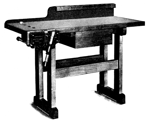
No.1 MANUAL TRAINING BENCH
| Length of Top | 50 inches |
| Width of Top | 21 inches |
| Height | 32 inches |
These benches are made of selected hard maple throughout, and are fitted with our No. 60 rapid-acting vise. They are shipped knocked down and any boy can set them up. They are extremely strong and rigid, and with our steel and iron vise make an outfit practically indestructible. We make benches only fitted with our vises, and can furnish any style desired, either single or double. Cabinetmakers’, carvers’ or special designs made to order. Our prices are but little, if any, higher than asked for cheaply made benches with wooden vises or cheap cast-iron vises. This is an excellent bench to have about the house, and is suitable for boys from 6 years old to men of 60. They are superior benches for manual training and have plenty of capacity for the work.
Manufactured only by
W. G. TOLES & CO.
Irving Park....Chicago, Ill.
SEND FOR CATALOGUE.
Manual Training Schools
Should have the very best Hand
Saws that can be obtained....

We make a Specialty of furnishing the
Right Kind—with
proper shaped handles for youths and children,
and made
from our celebrated
TRADE
SILVER STEEL
MARK
which is the finest steel ever used in saws.
Atkins Quality Stands at the Head
MANUFACTURED ONLY BY
E. C. Atkins & Co., Inc’p’d.
FACTORIES
Indianapolis, Ind.
BRANCH HOUSES:
Memphis, Tenn. Minneapolis, Minn. Atlanta, Ga.
Portland, Or., New York City.
OUR MOTTO:
“Atkins Always Ahead”
SIX! SIX!
BRIGHT NEW
BOOKS
IN THE MISTY REALM OF FABLE
By Emma Robinson Kleckner
“The book contains all that is best in Mythology, and what it presents is made the most of in the way it is told.”—Wm. Hawley Smith, Author and Lecturer.
This book is admirably adapted as a Supplementary Header for fourth and fifth grades. Second Edition. Cloth. Eight full page illustrations. Many smaller ones. 160 pages, handsome cover, list 50 cents.
TURNING POINTS IN TEACHING
By D. C. Murphy, Ph. D.
Superintendent Training Department of Slippery Rock (Pa.)
State Normal School.
Dr. Murphy is a practical teacher; he knows the needs of teachers and has given them a book full of New Methods, Ideas, Anecdotes and Helps. Some of the chapters are: The First Day of School; Critical Moments in the School Room; Managing the Bad Boy; Managing the Bad Girl; Blue Monday. Cloth, 144 pages, 50 cents; paper, 25 cents.
THE STUDENT’S GUIDE TO MUSIC
By J. N. Whybark
In the Student’s Guide to Music we find just what its name indicates; all the necessary rudiments of music; talks on Voice Culture, Breathing and Theory; nearly 100 Exercises in Sight Singing for classes in unison; a Complete Dictionary of musical terms. Manila binding, 60 pages, 25 cents.
NORTON’S PRACTICAL STUDIES IN GRAMMAR
Theory and Practice are combined; principles and definitions given from the outset, but with little formality; abundance of easy examples for illustrations; varied selections from standard literature for grammatical and literary study. Large type; several full page and half page illustrations. Cloth, 215 pages, price 40 cents. If the book is adopted the amount paid for the first copy will be refunded.
MISS HAUCK’S NEW REPRODUCTION
STORIES FOR PRIMARY GRADES
150 original and rewritten stories. They embrace all subjects, as Little Stories about Nature, Stories about Animals, Children, Flowers, Trees, Birds, Leaves, etc. Price 15¢.
A NEW HELP IN UNITED STATES HISTORY
By O. H Marsh,
County Supt.,
Mills County, Ia.
This is not purposed as a patent method for teaching history, but is the result of long experience in the school room and in normal institutes. The Outlines are full, the Notes interesting, the Questions suggestive. Send 25 cents for a copy and if not fully up to expectations, return same.
Are You in the Dark as to where certain articles in your work may be found? Write us for Helps in School Entertainments, General Work, School Blanks, Text Books, School Supplies, Pictures, Supplementary Reading, Etc.
A. FLANAGAN CO. CHICAGO
THE NEW ARITHMETICS
THE NEW PRACTICAL ARITHMETIC
By A. W. Rich, Professor of Mathematics
in the Iowa State Normal School.
This book is the result of practical work in the class room, and furnishes a complete course for all ordinary purposes.
Among the Features of Special Note are:
1. A set of tables and drills for mental work. These cover the essential operations of arithmetic and are designed to make the pupil proficient in the shortest time possible.
2. A presentation of the necessary definitions, principles, and rules in compact form so as to indicate clearly the arithmetical elements and relations.
3. A great number of model problem solutions. The scope, the varied character, and the helpfulness of these emphasize the thought side, and are of the highest value in developing the reasoning powers.
4. A large variety of Drill Tables, Test Problems, and other means of testing the pupil’s power as well as giving him mastery over the subject.
Cloth, 5 × 7½ inches. 222 pages. Price, 50 cents.
THE NEW HIGHER ARITHMETIC
The need of a good, practical, and suggestive higher text in arithmetic has long been felt. Not a book of catch problems, or a book filled with curious or obsolete matter is here presented; but a helpful, inspiring, useful text-book.
A Special Feature May be Mentioned:
The Model Solution found so valuable in the New Practical Arithmetic, has been carried forward in this work. To this has been added a feature known as “indicated work,” inventional in its nature, by which the pupil is taught to formulate his problems and to express them in clear and definite language.
This work is regarded as of high value in enabling a pupil to determine promptly the conditions of a problem, and to see the end from the beginning and then proceed by logical steps from the beginning to the end.
Cloth, 5 × 7½ inches. 320 pages. Price, 75 cents.
A copy of both books for $1.00. If adopted or returned money will be refunded.
Liberal Terms for Introduction and Exchange.
A. FLANAGAN CO. CHICAGO
Transcriber’s Notes:
The illustrations have been moved so that they do not break up paragraphs and so that they are next to the text they illustrate.
Typographical and punctuation errors have been silently corrected.