Copyright, Ewing Galloway
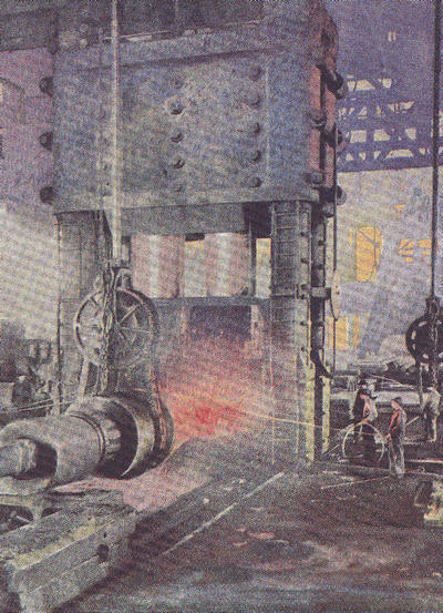
The drop forge. A fourteen-ton hydraulic press is employed in forging an immense open hearth steel plate.
Popular Science Library
EDITOR-IN-CHIEF
GARRETT P. SERVISS
AUTHORS
WILLIAM J. MILLER HIPPOLYTE GRUENER A. RUSSELL BOND
D. W. HERING LOOMIS HAVEMEYER ERNEST G. MARTIN
ARTHUR SELWYN-BROWN ROBERT CHENAULT GIVLER
ERNEST INGERSOLL WILFRED MASON BARTON
WILLIAM B. SCOTT ERNEST J. STREUBEL
NORMAN TAYLOR DAVID TODD
CHARLES FITZHUGH TALMAN
ROBIN BEACH
ARRANGED IN SIXTEEN VOLUMES
WITH A HISTORY OF SCIENCE, GLOSSARIES
AND A GENERAL INDEX
ILLUSTRATED

VOLUME FIVE
P. F. COLLIER & SON COMPANY
NEW YORK
Copyright 1922
By P. F. Collier & Son Company
MANUFACTURED IN U. S. A.
MECHANICS
The Science of Machinery
BY
A. RUSSELL BOND
Formerly Managing Editor, Scientific American

P. F. COLLIER & SON COMPANY
NEW YORK
PREFACE
ALTHOUGH strictly speaking the term “Mechanics” applies to that branch of Physics that deals with the actions of forces on material bodies, originally the word had a broader meaning embracing all machinery and mechanical inventions. To-day popular usage is restoring to the term its original broad interpretation, and it is in this popular but rather unorthodox sense that “Mechanics” has been chosen as the title of this book; for although certain elementary principles of mechanics are described and explained, the major portion of the book deals with machines and their evolution to their present stage of perfection.
Machines are man’s creation, and yet in a sense the man of to-day is a machine product; for modern civilization owes its material and in large measure its esthetic development to machinery. The story of machinery, from primitive man’s first attempts to augment his physical powers with mechanical aids down to the present era of gigantic, steel-muscled machinery and marvelously intricate mechanisms, is the story of human progress. It is this story that we have endeavored to tell in the following pages, but the subject is too large to be covered in a single volume or even a dozen volumes. Under the circumstances we have been obliged to confine ourselves to a mere outline, selecting certain avenues of progress more marked than others and presenting brief sketch maps of them. We have aimed[4] in this way to give a bird’s-eye view of the whole story of human progress in things material.
The book has not been written for the mechanical engineer, but for the layman who would learn of the mechanical contrivances that contribute to his material welfare; hence technical terms have been avoided, as far as possible, and where unavoidable have been explained and defined.
A. Russell Bond
CONTENTS
| CHAPTER | PAGE | |
| I. | Tool-Making Animals | 9 |
| II. | The Anatomy of a Machine | 20 |
| III. | Machines for Making Machines | 42 |
| IV. | Counting Seconds | 57 |
| V. | Putting Rivers to Work | 75 |
| VI. | Liquid Levers and Gears | 94 |
| VII. | Air vs. Water | 109 |
| VIII. | Air Springs and Cushions | 126 |
| IX. | Power from Heat | 139 |
| X. | Burning Fuel in the Engine Cylinder | 155 |
| XI. | When Coal and Oil Are Exhausted | 171 |
| XII. | Invasion of the Sea | 182 |
| XIII. | Sliding, Rolling, Walking, and Creeping | 203 |
| XIV. | Invasion of the Sky | 219 |
| XV. | Helping the Farmer | 239 |
| XVI. | Machining the Earth | 251 |
| XVII. | From Fiber to Fabric | 268 |
| XVIII. | The Making of Paper | 289 |
| XIX. | Typesetting and Printing Machinery | 300 |
| XX. | Cast Iron, Wrought Iron, and Steel | 314 |
| XXI. | Animated Machinery | 326 |
| XXII. | Heat Vacuums | 345 |
| XXIII. | Engines of Destruction | 359 |
| XXIV. | Summary of Mechanical Progress | 376 |
LIST OF ILLUSTRATIONS
| The Drop Forge—Forging a Steel Plate | Frontispiece |
| FACING PAGE | |
| Raising Water with a Chain of Pots—a Primitive Pump Used in Egypt | 32 |
| Horse-Operated Chain Pump Used in Greece | 32 |
| Multiple Spindle Drill in a Motor Car Factory | 33 |
| Bucket of a Giant Dredge with Its Jaws Wide Open | 64 |
| Gold Dredge Eating Its Way Through River Sands | 65 |
| Suction Dredge Excavating a Channel and Building New Land | 65 |
| Air Lock of a Pneumatic Caisson | 96 |
| Subaqueous Tunnel Showing the Shield in the Background | 97 |
| Wharf Protected by a Pneumatic Breakwater | 128 |
| Sun-Power Plant in Egypt | 129 |
| Close-Up of One of the Reflectors of a Sun-Power Plant | 129 |
| Giant Caproni Hydroaeroplane | 160 |
| Concrete Steamship “Faith” | 161 |
| “Virginian,” the Largest Locomotive in the World | 161 |
| Loom Provided with a Jacquard Attachment | 224 |
| Battery of Mule Spinning Frames | 225 |
| Jacquard Attachment for Loom | 225 |
| Digging a Trench with a Machine of the Chain Type | 256 |
| Multiple Plowing on a Western Wheat Field | 257 |
| Sawing Logs of Pulpwood into 16-Inch Lengths | 288 |
| Heater in a Pulp Mill Where the Wood Pulp Is Mixed with Clay | 288 |
| Modern Fourdrinier Paper-Making Machines[8] | 289 |
| Molten Metal from a Blast Furnace | 320 |
| Bessemer Converter Blowing Air Through a Mass of Molten Iron | 320 |
| Steel Beam Passing Through the Finishing Rolls | 321 |
| Compositor at Work on a Linotype Machine | 352 |
| The Optophone, Which Enables the Blind to Read Print | 353 |
| Blind Man Reading with His Ears | 353 |
CHAPTER I
TOOL-MAKING ANIMALS
WHEN we review the marvelous achievements of modern civilization we are quite willing to agree with the ancient psalmist that man is “little lower than the angels.” But at the other end of the scale our complacency is liable to receive a rude shock; apparently the boundary between man and beast is not so very easy to draw.
We used to be told that one important superiority of mankind lies in the fact that he makes use of tools, while the beast never uses any implement except those that nature has furnished him as part of his own organism. But a gorilla will throw stones at his enemy; and he knows how to brandish a club and use it with telling force. Some of the apes are known to use sticks to knock down fruit which is out of the reach of their hands, and they will crack nuts with a stone. Clearly these animals are tool users. A very intelligent orang-utan in the Bronx Zoölogical Garden, New York, after trying for days to wrench off a bracket from the wall of his cage eventually used the horizontal bar of his trapeze as a lever and with it pried the offending bracket from its fastenings. Here was real invention and the discovery of the principle of leverage. The great black arara cockatoo of New Guinea uses his beak as a saw to weaken the shells of hard nuts, and to keep his bill from slipping off the smooth[10] shell he is ingenious enough to wrap a leaf around the nut to hold it steady.
Even in the insect world we find creatures resourceful enough to make use of tools. Prof. Franz Doflein of the University of Breslau tells of an interesting study of certain ants, known as the Oecophylla smaragdina, who build their nests in bushes by fastening leaves together with fine threads. But the ants that build the nests cannot spin these threads, because they possess no spinning glands. They must depend upon their larvæ for this product. When a rent was made in one of these nests, a band of the tiny creatures ranged themselves side by side along the torn edge of the leaf and reached across the gap until they could catch hold of the opposite edge with their mandibles. Then they drew back step by step, with perfect teamwork, until the two edges were brought together. In the meantime, other ants had rushed to the nursery and each one had picked up a larva, not with the idea of bearing it off to safety, but in order that the babies might spin the thread which the adult ants were unable to do. The larvæ were carried to the breach in the nest and moved back and forth across the rent. They were pressed first against one side of the tear and then the other and all the while were squeezed tightly, evidently with the purpose of making them spin. Gradually a fine silky web was woven across the torn leaf and eventually the rent was completely patched.
Unquestionably these little ants are tool-using animals, because they make their larvæ serve as spinning spindles and also as weavers’ shuttles. However, this can hardly be cited as a point in common with even the lowest type of man, for the ants merely use the tools they find at their disposal.[11] They certainly cannot be credited with having produced or even improved the tool which they use, whereas even in the most primitive of men we find that the tools used are not only carefully selected for the work to be performed, but are actually, shaped, be it ever so crudely, to suit the job.
Clearly we must shift the boundary between man and beast, distinguishing the former as the creature who artificially improves his tools. But even here it is not absolutely certain that the boundary will stand. Wilhelm Boelsche, a well-known German writer on natural history, calls attention to the “blacksmith woodpecker” which will thrust hard pine nuts into cracks in the trunk of a tree, so that they are held as if in a vise, enabling the bird to operate upon the seed more easily. Furthermore, this woodpecker will actually make a hole in the tree to receive the nut if there is not a hole or crack handy, so that evidently this animal does produce or artificially improve the tool that it uses.
There are a few such examples in nature, just enough to cast a bit of uncertainty on the boundary we have set. But although the actual line of demarcation may not be clear, there is no question but that the lowest type of humanity now existent, or of which we have any record, is or was a tool maker. Chipped stones evidently fashioned by man for some useful purpose are found even in the remains of the Middle Tertiary Epoch. The spirit of inquiry, of experiment, of invention, and the ambition to dominate over other members of the animal kingdom or over the obstacles imposed by nature, are to be found more or less active among all peoples, no matter how lowly a position they may occupy in the scale of civilization.
WAR AS A STIMULUS OF INVENTION
The most primitive implements were probably developed for the purpose of war. From the very earliest times, down to the present day, war has been a most potent stimulus of invention. The first tools ever used were probably intended to enable the user to cope with dangerous enemies. They marked the first stage in the conquest of brain over mere brawn. The primitive weapons were used not only in fighting other men, but in fighting off dangerous animals, and then in hunting animals for food. No doubt the first implement ever used was a club, which gave a real advantage over the unarmed, scratching, tearing, and biting enemy. This was a lever which increased the reach of the fighter, and also increased the power of his blow. The heavier the club, the more dangerous the weapon, particularly when most of the weight was centered at the outer end of the stick. But he was a real genius who first fastened a rock to the end of his club.
THE ART OF BREAKING STONES
Then arose the art of breaking stones—breaking them skillfully, so as to form a jagged cutting edge. When man began to fashion tools of stone he left imperishable records of his craftsmanship which enable us to trace his progress in invention. The first finished tool we find was the fist hatchet—a stone roughly chipped to form a cutting edge and of convenient shape for the grasp of the hand. This primitive tool very slowly, through a period covering thousands of years, developed into all manner of cutting implements, some with handles of wood and bone. The ax head was followed by the spearhead[13] and this finally by the arrowhead, showing that man had at last found a mechanical substitute for his muscles to hurl projectiles farther and with greater accuracy than he could throw them by hand.
We marvel at the resourcefulness and skill of the primitive savage in working so difficult a material as stone. It would baffle a modern mechanic to be required to shape a piece of flint into an arrowhead with no other tool than a piece of bone. He is so accustomed to using tools which are harder than the material they are intended to shape that he cannot conceive of making any impression upon a piece of flint with a piece of bone, to say nothing of a stick of hard wood, and yet such tools were used away back in the Stone Age. At first stones were roughly shaped by hammering them together. Then the artisans became more skilled. They discovered that certain stones could be chipped more regularly and evenly, and the art of flaking off chips of flint sprang up. Some specimens that belonged to ages long preceding that of recorded history are beautifully done. The spearheads are symmetrically shaped like a long narrow leaf, and the stone is evenly furrowed on both sides with a keen edge all around.
Not only did primitive artisans shape the stone implements with hammer blows, but they learned how to shape stone by pressure as well, using a tool that was relatively soft. It is not a very difficult matter to shape even so hard a substance as glass merely by pressure. If a piece of glass is laid on a table with its edge slightly overhanging that of the table, it is possible to chip off the overhanging edge by pressing a nail or even a hard stick of wood against this edge. A small flake of glass is thus removed, and, by continuing the process, arrowheads of any[14] shape may be formed. The tool is placed not against the upper surface of the glass, but against the edge of the glass, so that only the lower surface of it is split or flaked off. Then the glass is turned over and a chip is taken off the opposite face.
In the Middle Stone Age we find the primitive craftsman equipped with a very complete assortment of stone tools. He had hammers, chisels, scrapers, drills, and polishing tools. He knew how to make useful household implements, such as spoons and ladles, out of bone. He polished his work and ornamented the implements with carvings of animals. Ivory pins and needles show that he had begun to make himself clothing from the skins of animals and that he sewed them together with thongs or tendons.
In the Late Stone Age he had learned how to make vessels of fire-baked clay. His axes were ground to a sharp edge, and he bored holes in the ax head to receive the ax handle. The Swiss lake dwellers built houses of wood and fitted them with all sorts of wooden furniture carved with stone tools. Among the remains of these interesting settlements may be found balls of clay which, from the fact that one of them was discovered with a spool of flax still attached to it, were evidently used as spinning “whorls” used for spinning flax into thread. Clothing of skins was giving way to or being supplemented with clothing of woven fabric.
DISCOVERY OF THE LEVER AND THE WEDGE
Prior to the Stone Age the club was undoubtedly used, in time of peace—if there ever was a time of peace in those days—to batter down trees, to beat through entanglements and to dislodge great stones.[15] Here the first idea of leverage was evidently employed. The club with a rock tied to it, particularly if the rock was shaped with a sharp edge, made a better implement for hewing trees. It is quite probable that soon after this stage of development had been reached, some one discovered the use of the wedge, particularly in splitting timber. Of course, no one realized in those early days why it was that he could pry up a greater weight with a lever than he could lift directly by hand, or why he could split open a log by driving wedges into it. The art of mechanics was in existence long ages before science of mechanics began to be studied. But it was not until men began to look into the why of things that rapid progress was made.
We can go on endlessly with our speculations on the evolution of tools and machinery up to the time when historians began to record the mechanical achievements of man. Unfortunately even after historians began to write they were so filled with admiration for the destructive work of man that they had no time to record his constructive work. The warrior who spread havoc and terror received all the glory, and his deeds were written on parchment, inscribed in clay and carved in stone; but the humble artisan was not worthy of mention. Even when the science of mechanics came to be studied, it was shrouded in a veil of mystery, and it was beneath the dignity of the man of science to impart his knowledge to the artisan. There was a lack of cooperation between science and industry that has persisted to a certain extent even up to the present time. Some of the most ingenious inventions of the ancients were employed by a corrupt and crafty priesthood to produce apparently miraculous effects[16] and hoodwink the general public; and so, in looking back to the early days of mechanics, we are obliged to draw upon our imagination to trace its evolution, supplementing this by a study of the tools of primitive people of more recent time. Practically every form of hand tool we now use must have been known to the ancient artisan.
INVENTION OF THE WHEEL
We are not going to attempt to write a history of the evolution of machinery, but there is one invention whose origin is lost in the remote prehistoric ages which deserves more than passing attention. It is a pity that we have no clue as to who invented the wheel or how this most important element that enters into the construction of nearly all machinery was evolved. The invention called for a remarkable degree of originality. There is nothing like a wheel in nature. Levers we have in our own physical frame. But a wheel is something that is distinctly a human creation. Whoever invented it must have been a real genius, a James Watt or a Thomas Edison of his day. Certainly we owe more to the invention of the wheel than we do even to so revolutionary a machine as the steam engine, or the flying machine. How it was ever first conceived is a mystery. Maybe this primeval genius got his idea from seeing a stone rolling downhill, or he may have seen a tumbling weed rolling along the ground before the wind. It may be that the forerunner of the wheel was a roller shaped out of a log, for certainly primitive civilization must have advanced enough to have known how to hew timber before it would have been capable of fashioning a wheel. Some observant man might have noticed that he could drag a heavy[17] timber over a rolling log much more easily than he could along the bare ground, and gradually the roller evolved into a wheel.
We can speculate upon the evolution of vehicles and transportation, once the wheel was invented. Of course, the first method of transporting loads was to carry them in the arms. Possibly loads were placed on skids and dragged along by one end. Away back in early times, it was discovered that two persons could carry more than twice as much as one, if the load were placed on a couple of poles. There was no friction to contend with, and not only was the load cut in two, because each man bore half of it, but the position of the load was such that it could be borne more easily. After the wheel was discovered, some one must have conceived of the idea of dispensing with an assistant by placing a wheel between the poles of the stretcher, thus making a crude wheelbarrow. It is more likely that two wheels were first used, making a cart of the stretcher, because the crude workmen of those days could hardly have produced anything but a very wobbly wheelbarrow. At any rate, the wheel, or pair of wheels, robbed one man of his job. Only one bearer was required where before two had been used. Labor costs were immediately reduced 50 per cent.
DISPLACING MEN WITH MACHINES
In the very earliest days of invention machines began to displace men. Had there been unions in those days, no doubt there would have been strenuous opposition to the introduction of this substitute for an honest worker. But among the ancients, even more than at the present time, invention meant greater production rather than less work, because[18] the laborer of that time was not a hired man but a slave. There was no object in cutting down labor when it cost practically nothing. The only stimulus to invention was greater production.
The invention of the wheel meant the dawn of transportation, which is the backbone of civilization, and from it resulted no end of other inventions. It made it possible for communities to come into closer touch with each other. It meant circulation—an interchange of knowledge and of products. Food was transported from one locality to another, enabling certain communities to dispense with agricultural work and specialize in certain lines of manufacture; for they could barter their products for food raised by other communities. There are some tribes to-day which are most backward because they are separated from other tribes by rivers, while other tribes similarly placed owe their progress to the fact that they have developed sufficient skill to build crude bridges and thus gain access to the outside world.
RAISING WATER
In Egypt the wheel had a wonderful effect on agriculture. In that dry land water is, and always has been, most precious. No wonder the Nile was venerated! It meant life—life to crops, and hence life to man. How to raise water from this stream of life in time of drought was the great problem of the Egyptian. As slave labor was cheap, it was customary to haul up the precious water, a bucket at a time, and pour it over the fields. Then some one discovered that this process could be simplified by using a shadoof or swape; in other words, a long pole fulcrumed near one end, with a heavy rock for a counterbalance lashed to the shorter arm, and a bucket[19] tied by a long rope to the longer arm of the lever. This primitive machine is still to be found in some rural districts. With this contrivance, a heavier load could be lifted than by hand, because, when raising the bucket, the weight of the rock would assist in lifting the water. After the swape came all manner of ingenious devices for lifting the water. There were seesaw arrangements which would scoop up some of the water at each oscillation of the seesaw, and in one ingenious contrivance there was a succession of seesaws by which the water was raised to a considerable height, whence it poured down into ditches that irrigated the fields.
Then some one invented a water wheel or a great wheel, fitted with buckets, which was turned by human or ox power, and which poured a steady stream of water into the irrigating ditches.
But the greatest invention was that of the engineer who actually made the river turn the wheel. It was probably on the Nile that the noria, as this machine was called, was first put into service.
The wheel was provided with paddles, so that the current made it revolve, and the water spilled out of the buckets into a trough as they were turned over by the wheel. We can imagine the triumph of the ancient inventor who developed that machine. True, the river might arise in its wrath now and then and wreck the machine, but in wrecking the wheel it had to flood the land, which, after all, was exactly what was aimed at. The anger of the river was short-lived; it soon quieted down and went on placidly turning the wheel which robbed it of the precious water. It was a great event in the history of engineering. The Nile had been harnessed. One of the great powers of nature had been set to work.
CHAPTER II
THE ANATOMY OF A MACHINE
EVERY animal is a complex machine, provided with its own motive power and a brain for directing the operation of its own mechanical elements. Not satisfied with the mechanism that nature has put into the human machine, man has reached for other elements and devised mechanisms of his own in order to supplement the human machine and increase its efficiency. At first, as we have seen, these elements were hand tools of the crudest sort; but they were gradually improved and then they were combined into what we term machines. In developing these machines, he naturally took his own system as a pattern and was guided to a large extent by an examination of his own physical structure. We see this very clearly in the names of the different parts of machinery, which are taken from the names of similar parts in the human frame. Almost every member of the body is used in mechanical terminology. For instance, we have the “head” and the “foot,” the “arms” and the “legs,” the “fingers” and the “ankles,” “elbows,” “shoulders,” “trunk,” “hips,” and various parts of the face, such as the “eyes,” “ears,” “nose,” “mouth,” “teeth,” “lips,” and even the “gums,” to indicate parts of machinery which have some remote resemblance to these features.
Before we can understand machinery we must have some general knowledge of the elements of[21] which it is composed. Probably most of the readers of this book already possess a fair knowledge of machine elements and mechanical movements and they can well afford to skip this chapter. However, for the benefit of the uninitiated, we must put a machine on the operating table, dissect it, and explain its anatomical structure. We cannot attempt a very detailed study, but will confine ourselves to the most important elements.
Every machine is made up of movable parts and fixed parts, the latter serving to guide or constrain the motion of the former; for no combination of elements will constitute a machine unless the parts are constrained to move in certain predetermined directions.
THE LEVER
Among the moving elements the first to be considered is the lever, which really forms a broad classification comprising many elements that will hardly be recognized as levers at first blush. Levers in some form are to be found in practically every machine. A wheel, a gear, and a pulley are really levers in disguise, as will be explained presently.
Of course everyone knows that a simple lever consists of a rigid bar that swings on a fulcrum. The fulcrum may be a knife edge, a shaft passing through the bar or any element on which the bar can be swung or oscillated. The purpose of the lever is to give a certain advantage in the application of a force to a load. This may be a change of speed and distance of travel, and hence of power, or merely a change of direction.
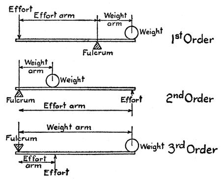
FIG. 1.—THREE ORDERS OF SIMPLE LEVERS
There are three types or orders of levers produced by varying the relative positions of the points where the fulcrum, the force or effort, and the weight or load are applied. These are shown in Figure 1. In the lever of the first order the fulcrum is placed between the effort and the weight; in the lever of the second order the weight is applied between the fulcrum and the effort; and in the lever of the third order the effort is applied between the fulcrum and the weight. In each case that part of the lever which extends from the fulcrum to the point where the effort is applied is called the effort arm, and that which extends from the fulcrum to the point where the weight is supported is the weight arm. The weight that can be lifted with a given effort depends upon the ratio of the effort arm to the weight arm. If the two arms are of equal length, the effort is equal to the weight, but twice the weight can be lifted with the same effort if the effort arm is twice as long as the weight arm. You can lift a ton with[23] an effort of only 100 pounds if your effort arm is twenty times as long as your weight arm but the end of your effort arm would have to move twenty inches to raise the ton weight one inch. We are assuming in all these cases that the lever itself has no weight and that there is no friction at the fulcrum.
Of course levers are not used merely for the purpose of lifting weight, but to overcome any resistance or merely to apply pressure upon an object. In almost every household we may find examples of the three orders of levers. A pair of shears, for instance, is composed of two levers of the first order, swinging on a common fulcrum. The effort is applied at the handles, and the weight or load is the material that is cut by the blades or, speaking more technically, the handles are the effort arms and the blades are the weight arms. A material that is too tough to be cut at the tip ends of the blades may be easily cut if we move it in near the fulcrum or pin that hinges the blades together; for by doing this we shorten the weight arms, because the weight arm is measured not to the end of the blade, but to the point where it is cutting into the material. To cut very tough material, such as heavy tin or sheet steel, we use long-handled short-bladed shears. The cutting pressure depends upon the ratio of the effort arm to the weight arm. If the effort arms are twice as long as the weight arms, the cutting pressure is twice as great as that applied at the handles.
A nutcracker consists of a pair of levers of the second order. The fulcrum is at one end and the effort or pressure is applied at the opposite end of the levers or handles, while the equivalent of the weight (in this case the nut) is placed between the effort and the fulcrum. Again the effort arm is[24] measured from the fulcrum or hinge pin of the tool to the point where the hand pressure is applied, and the weight arm is measured from the fulcrum to the nut. The effort arm may be four or five times as long as the weight arm, so that the pressure exerted on the nut is four or five times as great as that exerted by the hand on the ends of the handles.
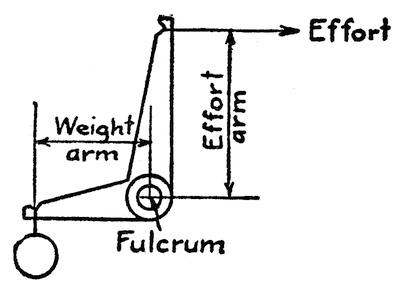
FIG. 2.—AN ANGULAR OR BELL-CRANK LEVER
In the case of a pair of sugar tongs we have another tool something like the nutcracker in construction, but here the weight, i.e., the lump of sugar, is seized by the ends of the tongs while the hand pressure is applied somewhere between the fulcrum and the weight. Hence we have here a lever or pair of levers of the third order. The effort arm of a pair of tongs is always shorter than the weight arm and the pressure on the sugar lump is always less than that exerted on the tongs by the hand. Evidently the most powerful tool of the three is the nutcracker, because the effort arms extend over the full length of the tool and are always longer than the weight arms.
A lever need not consist of a straight bar; the effort arm may form an angle with the weight arm, forming what is known as an angular or bell-crank[25] lever (Figure 2). When a common claw hammer is used to pull out a nail, the claws that slip under the head of the nail form the weight arm and the hammer handle the effort arm. A horizontal pull on the handle produces a vertical lift on the nail.
Sometimes two or more levers are interconnected, as in Figure 3, the effort arm of one being linked to the weight arm of the other. This serves to increase the lifting force at the weight and at the same time keep the mechanism within compact limits. Such compounding can go on indefinitely and is subject to all sorts of variations.
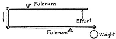
FIG. 3.—COMPOUND LEVERAGE
One thing we must not forget, and it is a matter that is commonly overlooked by perpetual motion cranks, namely, that while a pound of pressure on the effort arm may be made to lift two, four, or a hundred times as many pounds on the weight arm by varying the relative length of these arms, it has to move two, four, or a hundred times as far as the weight arm, so that the work done on one side of the fulcrum is always exactly equal to that done on the other side.
CONTINUOUS REVOLVING LEVERAGE

FIG. 4.—PRIMITIVE GEAR WHEELS—TWO COACTING GROUPS OF LEVERS
If we take a number of levers radiating from a common fulcrum like the spokes of a carriage wheel, we have a primitive gear wheel. Two such groups of levers may be mounted on parallel shafts so that when one is turned its spokes will successively engage the spokes of the other group and make the latter turn (see Figure 4). Each spoke is first an effort arm on one side of the wheel and then a weight arm as it turns around to the other side of the wheel, and as the effort arms and weight arms are of the same length there is no multiplication of power. A pound on one side of the wheel cannot lift more than a pound on the other. The driven wheel receives the same power as the driving wheel except for such loss as may be due to friction at the bearings or where the spokes contact. The only advantage of such a pair of gears is that the direction of rotation of the driven wheel is the reverse of that of the driving wheel. If the spokes of one wheel are longer than those of the other, we have at once a variation in the rate of rotation proportional to the relative diameters of the two wheels. In Figure 5, for instance,[27] the diameter of the driving wheel A is twice the diameter of the driven gear B, and so, for each revolution of A, B must make two revolutions, i.e., the driver must make two revolutions for each revolution of the driven wheel. In other words, the speed of revolution is doubled. However, if we make B the driver the speed of the driven wheel A will be half of that of wheel B.
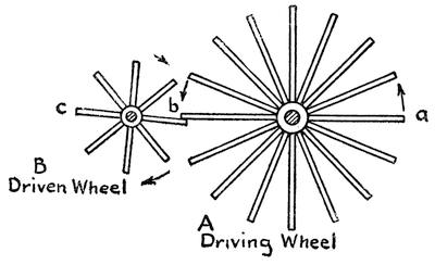
FIG. 5.—COACTING LEVERS OF UNEQUAL LENGTH
In primitive machines spoke gears were seldom mounted on parallel shafts because of the difficulty of keeping the spokes in alignment. Instead, one shaft was mounted at right angles to the other so that one set of spokes would cross the other (Figure 6), thus producing the equivalent of a bevel gear. This was of advantage in changing the plane of rotation. A later development was the barrel or lantern gear, which permitted transfer of power without changing the plane of rotation. A cylindrical bundle of rods constituted one of the wheels (as shown in Figure 7). Instead of being crudely formed of spokes, the other wheel sometimes consisted of a[28] disk with pins radiating from its rim. Such gears in far more refined form are still used in modern clocks and watches. A still further development for transmitting motion to a plane at right angles to that of the driving shaft is shown in Figure 8. Here we have a crown gear in which the pins instead of radiating from the periphery of the disk project from the side face of the gear.
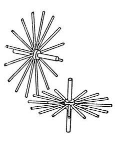
FIG. 6.—PRIMITIVE EQUIVALENT OF THE BEVEL GEAR
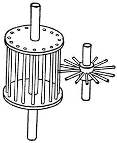
FIG. 7.—PRIMITIVE LANTERN GEAR
Turning back to our first spoked wheels, it is very evident that we may put a rim over the spokes or even fill in between the spokes and convert the wheels into solid disks that are in frictional engagement with each other without getting away from the fact that we are dealing with levers. Each wheel, then, consists of a continuous revolving lever. Friction gears are used quite commonly in machinery when it is desirable to have the wheels slip if subjected to excessive strain.
TOOTHED GEARS
By forming teeth on one gear to mesh between similar teeth on the other, we convert the friction gears into a pair of spur gears (Figure 9). We need not go into the intricacies of the form of gear teeth. They are designed to be in continuous rolling contact while they are in mesh. The novice is apt to call all spur gears “cogwheels” and gear-teeth “cogs.” Mechanics, however, recognize a difference between cog wheels and spur wheels. In the former, the teeth, or cogs, are not cast upon or cut out of the wheel body, but are separate pieces fitted to the wheel. Such wheels are found in old water mills. They consist of wooden wheels with iron or steel teeth mortised in the wooden rim of the wheel. In general it is safer to speak of spur gears because there are few cogwheels now in use.
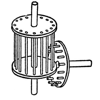
FIG. 8.—CROWN AND LANTERN GEAR
When a small gear engages a large one, the former is commonly known as a pinion.
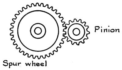
FIG. 9.—SPUR AND PINION GEAR
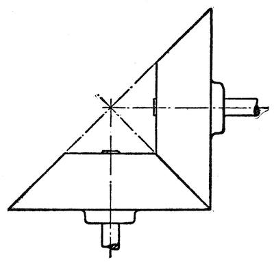
FIG. 10.—BEVEL FRICTION GEARS
If two friction wheels are to turn at right angles one to the other, they must have conical bearing surfaces, as in Figure 10. The angle between the shafts of the two gears and the relative size of the gears may be changed as desired, provided each cone surface has its apex at the intersection of the two shafts or axes. It is easy to understand how such conical friction gears may be converted into toothed bevel gears (Figure 11), by forming teeth on the conical[31] surfaces, and it will be evident that the teeth must taper toward the apex of the two cones. Two bevel gears of equal diameter, and with shafts set at right angles one to the other, are known as miter gears.
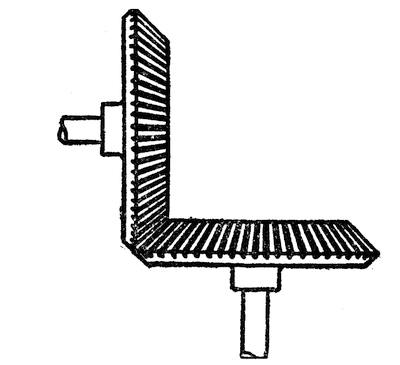
FIG. 11.—TOOTHED BEVEL GEARS
So far we have not shown any combination of gearing that will multiply power. In Figure 5, the driver A is twice the diameter of the driven wheel B, and the latter makes two revolutions for one of A, but the speed at the periphery of the two wheels is the same. A pull of one pound at the point a produces a pressure of one pound at b, and this in turn produces a lift of one pound at c because the levers in each wheel are perfectly balanced, that is, each lever has equal effort and weight arms. The way to obtain an increase of power and of peripheral speed is to fasten two wheels of unequal diameters together on the same center and apply the effort to one of the wheels (as in Figure 12) and the weight to the other wheel. This gives us what is technically known as a wheel and axle. The dotted lines show that we have here a lever of the first order which can be used to multiply power in the same way that a bar lever does. If one wheel is twice the diameter[32] of the other then a pound of effort will lift two pounds of weight.
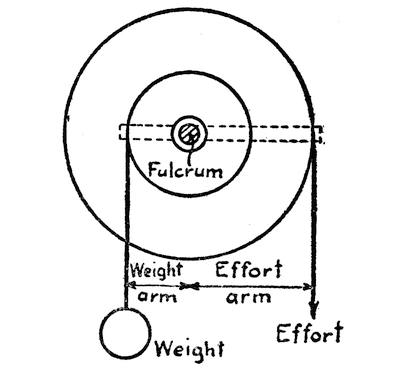
FIG. 12.—WHEEL AND AXLE OR REVOLVING LEVER OF FIRST ORDER
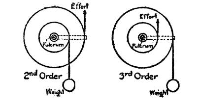
FIG. 13.—REVOLVING LEVERS OF THE 2D AND 3D ORDER
Figure 13 shows how the effort and weight can be shifted about in such fashion as to give us a lever of the second and one of the third order. The power may be enormously increased and the speed of the final wheel greatly reduced by setting up a train of gears in which the effort is received by the larger one of each couple and is delivered by the smaller one. In Figure 14 the smaller wheels are half the diameter of the larger ones. A pound of pressure at A will amount to 2 at B, 4 at C, 8 at D, 16 at E, and 32 at F. On the other hand, point A will have to move through 32 inches to make the point F move an inch.
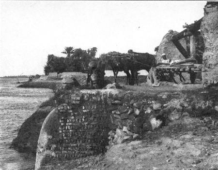
RAISING WATER WITH A CHAIN OF POTS
A primitive pump still used in Egypt
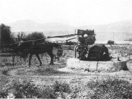
A HORSE-OPERATED CHAIN-PUMP USED IN GREECE
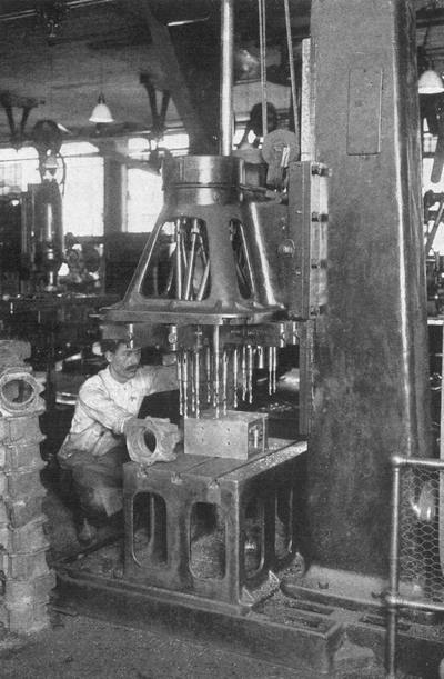
MULTIPLE SPINDLE DRILL IN MOTOR CAR FACTORY

FIG. 14.—A TRAIN OF SPUR GEARS
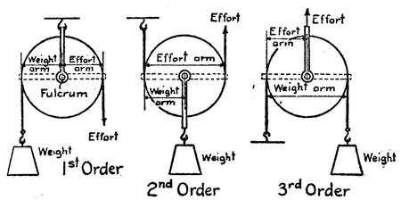
FIG. 15.—PULLEYS OF THE 1ST, 2D, AND 3D ORDERS
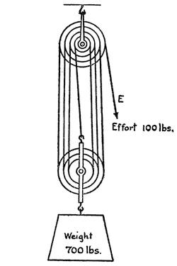
FIG. 16.—TYPICAL ARRANGEMENT OF BLOCK AND TACKLE
A pulley is merely a modification of the wheel. Figure 15 shows how it may be arranged to correspond to the three orders of simple levers. If the pulley axis is fixed, as in the first order, the effort and weight arms are equal and hence balanced. In the second order the wheel is bodily movable, hence one pound will raise two pounds of weight because the power arm is twice as long as the weight arm, while in the third order it takes two pounds of lift to raise one pound of weight. There is no end of possible combinations of pulleys which will multiply power in the same way that bar levers do when compounded. A common arrangement of block and tackle is given in Figure 16. There is a four-sheave pulley block above and a three-sheave block below, but in order to trace the rope clearly the pulley wheels or sheaves are represented as of different diameters. The arrangement consists of a series of levers of the first order in the upper pulley block coupled to a series of levers of the second order in the lower block. To find the weight that a given[35] power will lift, multiply the effort by the number of strands of rope that are supporting the weight. In this case there are seven such strands, not counting the strand E, to which the effort or pull is applied. This means that a pull of a hundred pounds at E will lift 700 pounds at W. Of course a pull of seven feet at E will raise the weight only one foot.
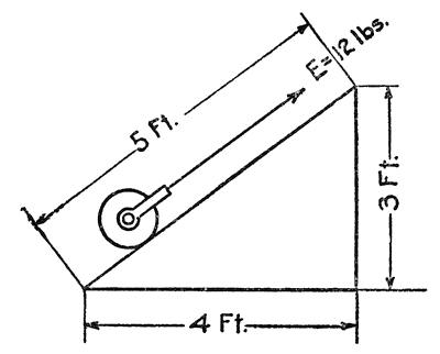
FIG. 17.—INCLINED PLANE WITH EFFORT PARALLEL TO THE INCLINED FACE
THE INCLINED PLANE AND ITS FAMILY
The inclined plane constitutes a second broad classification of machine elements. The wedge, the screw, the cam, and the eccentric, all belong to the family of the inclined plane.
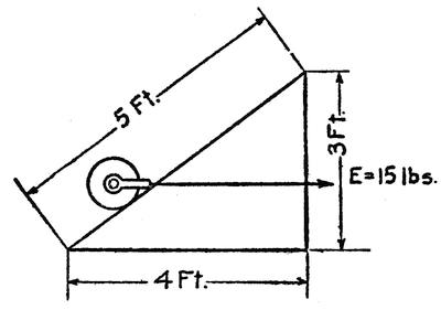
FIG. 18.—INCLINED PLANE WITH EFFORT PARALLEL TO THE BASE
A simple form of inclined plane is pictured in Figure 17, which shows a weight W being rolled up an incline. The effort required to carry it to the top of the incline depends, of course, upon the steepness of the incline. The drawing shows a rise of 3 feet on a slope 5 feet long, and the weight of the wheel is, say 20 pounds. To find the effort required, the weight is multiplied by the rise (20 × 3 = 60) and divided by the length of the slope (60/5 = 12) and we find that it takes only 12 pounds to roll the 20-pound wheel to the top of the incline. This holds true when the pull is parallel to the inclined face. If the pull is parallel to the base of the incline, as in Figure 18, we must divide by the length of the base instead of the length of the incline (60/4 = 15) and we find that it takes 15 pounds of effort to pull the weight up the incline. If the pull is exerted at an angle both to the base and the inclined face, we have a problem that is slightly more complicated and we need not go into it here because it involves a bit of trigonometry. In all cases, however, it may be noted that the amount of rope that is taken in, in hauling the weight up the incline, bears a definite relation to the amount of effort required to raise the weight. In Figure 17, 5 feet of rope must be pulled in, in order to raise the weight 3 feet, so that ⅗ of 20 or 12 pounds is all that is required to pull up the weight, while in Figure 18, 4 feet of rope is hauled in for a lift of 3 feet, so that ¾ of 20 or 15 pounds is required to pull up the weight. In this[37] respect the inclined plane is exactly like the lever or the pulley, for the effort multiplied by the distance through which it is exerted is always exactly equal to the weight multiplied by the distance through which it moves. Thus in Figure 17, the effort 12 pounds multiplied by the distance 5 = the weight 20 pounds times the distance 3, and in Figure 18, effort 15 x distance 4 = weight 20 x distance 3. Of course, we are ignoring the weight of the rope and the friction which, in actual practice, are important factors to be reckoned with.
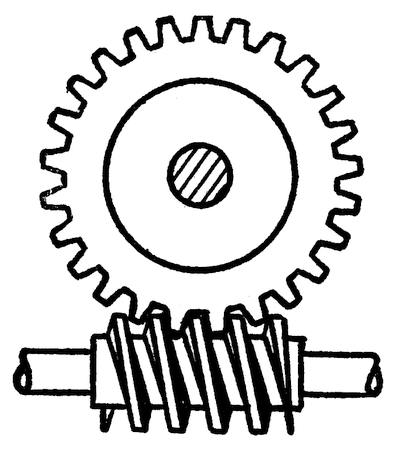
FIG. 19.—ENDLESS SCREW OR WORM GEAR
So far we have considered a fixed inclined plane, but when the inclined plane is moved between the weight and a fixed base it is known as a wedge, and in this case, too, the effort required to move the wedge multiplied by the distance the wedge moves is equal to the weight multiplied by the distance it is lifted.
The commonest form of inclined plane is the screw which is merely an inclined plane bent around a[38] cylinder. A screw engaging a toothed wheel, as in Figure 19, gives a combination known as an “endless screw,” or, more commonly, as a worm gear. The screw or worm is always the driver, and as it must make a complete turn to move the gear through a space of one tooth, the power of this combination is very great. It is practically impossible to turn the worm by using the gear wheel as a driver because the friction developed at the point where the worm and gear contact is very great. For this reason worm gearing is used in the steering gear of automobiles. The shaft of the steering wheel is fitted with a worm which meshes with a worm gear on the parts connected with the wheels. It is very easy to turn the wheels by operating the steering wheel, but if the wheels strike a rut or a stone they are not deflected from their course, because the worm makes it impossible for them to turn the steering wheel.
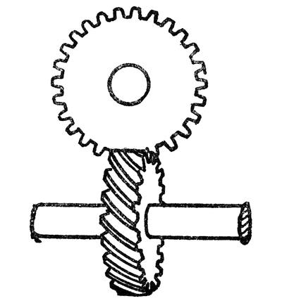
FIG. 20.—HELICAL OR SPIRAL GEARS
The spiral gear shown in Figure 20 is a cross between a worm gear and spur gear. The teeth are[39] spirals set at an angle of 45 degrees to the axis of the wheel. In this case either gear can be used to drive the other, and the advantage of such a pair is that power is transmitted from one shaft to another in a different plane and at right angles to the first.
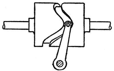
FIG. 21.—DRUM CAM
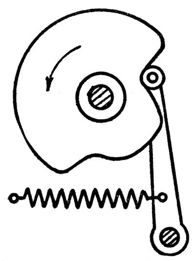
FIG. 22.—PROFILE OR DISK CAM
Cams are usually irregular revolving inclined planes. Figure 21, shows a cylinder or drum cam. A groove is cut in the cylindrical wall of the cam and an arm or lever is provided with a roller which[40] rolls in the groove. When the cam is revolved the lever is constrained to follow all the twists and turns of the groove. A different form of cam is shown in Figure 22. It is formed with an irregular periphery against which the roller is pressed by a spring. As the cam wheel revolves, the roller and the arm to which it is attached must move in and out over all the hills and valleys of the periphery. The cam is one of the most useful elements in modern machinery, for it provides a very simple means of producing the most complicated and irregular motions.
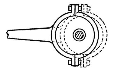
FIG. 23.—ECCENTRIC BY WHICH ROTARY MOTION IS CONVERTED INTO RECTILINEAR MOTION
We cannot attempt to describe all the different types of cams, but reference should be made to the eccentric, which is a form of cam commonly used to operate the valves of a steam engine. The cam in this case is a perfectly circular disk, but the shaft that turns it does not lie at the center of the disk, consequently an object bearing against the periphery must move toward and away from the center as the disk revolves. Instead of using a spring-pressed roller to bear against one side of the disk, the whole disk is encircled with a ring of steel known as an[41] eccentric strap. This strap is bolted to a valve rod and as the eccentric revolves the strap makes the valve rod move back and forth. (See Figure 23.)
A description of all the various combinations of gearing, link motions, ratchets, escapements, clutches, and miscellaneous movements would easily fill the rest of this book, and we must therefore content ourselves with this very brief survey of a few of the more important elements employed in the construction of modern machinery.
CHAPTER III
MACHINES FOR MAKING MACHINES
WHILE we may glory in the wonderful mechanical progress of to-day, we must not overlook the marvelous skill of the ancient artisan nor forget that it is to his inventive genius that we are indebted for practically every hand tool we possess. Only a few special tools owe their origin to the modern inventor. All the rest date back beyond the twilight of history. We have merely improved upon these tools by slight changes of design or the employment of better materials in their construction.
As users of these tools we cannot begin to compare with the skilled workman of ancient days. Our progress is shown not in the development of skill, but in the loss of it. We have taken the tool out of the human hand and put it into an inanimate machine. It is only very recently that the tool was delivered to the machine and that act marked the dawn of the present remarkable mechanical era.
Machines for making machines date back to the time of the early Egyptians. They had their pole lathes and bow drills, but these machines only partially relieved the workman of his labors, and the quality of the work still depended upon a degree of skill that was acquired only through years of patient apprenticeship.
The pole lathe, by the way, consisted merely of a pair of centers between which the work was[43] mounted, a pole attached to the ceiling and a strap or rope passed around the work and fastened at one end to a pole and at the other to a pedal resting against the floor. (See Figure 24.) When the pedal was depressed, the strap was pulled down and the work was revolved. On releasing the pedal, the spring of the pole pulled the strap up and reversed the rotation of the work. Thus by alternately depressing and releasing the pedal, the work was intermittently revolved against a chisel which was rested on a block and guided by the workman. Small work could be turned out on such a lathe with considerable precision, but when it came to large parts, particularly parts of steel, the workman was easily tired by the effort of operating the pedal and was apt to be irregular in the guiding of the tool.
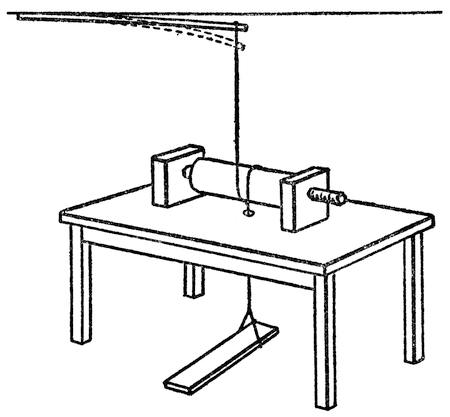
FIG. 24.—PRIMITIVE POLE LATHE
Up to the middle of the eighteenth century practically no advance had been made over the ancient[44] lathe of the Egyptians, and when, 150 years ago, the steam engine was invented the task of building the engine seemed almost insuperable.
James Watt was a maker of mathematical instruments, a man of great skill and precision as a craftsman, but he dealt with parts of small dimensions. When he conceived of his steam engine, he mentally pictured the various parts as turned out with all the accuracy and finish that was possible in the diminutive members of a scientific instrument. To him it seemed perfectly feasible to turn a cylinder which would be practically perfect in contour, and to fit it with a piston around which no steam could leak. With the lathe then in existence such a fit was easily possible on small work. But when he undertook to have the cylinder of his engine bored, he discovered that there was no machine that could begin to do the work properly. In fact, when Smeaton, who was a prominent engineer of that time, investigated Watt’s steam engine, he declared that it was such a complicated piece of work that neither tools nor workmen existed that could build it. In Watt’s first engine, the cylinder was only six inches in diameter and two feet long, and a special type of boring machine was devised to bore the forged cylinders. But the boring was so irregular that when the piston was inserted and the steam was turned on, nothing would stop the flow of steam that leaked around the piston. In vain did James Watt use cork, oiled rags, tow, paper, and even old hats to stop the leakage. However, the boring machine was improved and later a cylinder, eighteen inches in diameter, was bored with such accuracy that the large diameter exceeded the small diameter in the worst place by only ⅜ of an inch. This Watt considered a very good bit[45] of turning. To-day cylinders of that size that vary from true by half the thickness of the paper that this is printed on would be thrown out as defective.
It was in 1769 that Watt invented the steam engine, but that great event did not mark the dawn of the present era of machinery. For a quarter of a century thereafter there was little progress in the development of machine tools. A boring machine was built that did fair work. There were a few sawmills in which wind power was employed to drive the saw. But lathes were still driven by foot power and the cutting tool was still held and guided by hand.
MAUDSLEY’S “GO-CART”
The real father of the present era was a very clever British mechanical engineer, Henry Maudsley, who undertook to eliminate the uncertainties of the human hand by clamping the cutting tool of the lathe in a rest and arranging the rest to slide along the length of the lathe or transversely toward or away from the center. These two motions made it possible to accomplish all that the workman could accomplish by hand and at the same time the tool was held so firmly that accuracy and precision of turning was assured. Furthermore, he provided this slide rest with a nut that engaged a screw driven through suitable gearing by the lathe spindle. Then, as the work revolved, the slide rest was compelled to move along the bed of the lathe at a uniform rate. By varying the gearing, the speed of the slide rest and the tool it carried could be varied at will, thus making it possible to cut screw threads of any pitch desired with a degree of accuracy unattainable by hand.
Remarkable as was this improvement, it met with the usual opposition that every real advance in machinery received in those days. People referred to the slide rest as Maudsley’s “go-cart,” but it proved such an important element of the lathe and so very valuable that before long it was universally adopted. From that time on the skill of the workman began to lose its importance. The man began to give way to the machine. Precision was possible in large as well as small work. The human element was also dispensed with in the driving of the lathe. The foot pedal was superseded by the steam engine, and the machine came to be known as the engine lathe.
There are many ways of working metals now in common use. Metals may be cast in a molten state, or they may be pressed and molded into shape in a cold state, or they may be hammered either cold or hot, but in nearly all cases in which metal is removed in order to form a piece of work, the chisel is used as a cutting instrument. This is perfectly apparent in lathes and planers, but not quite so apparent in sawing, drilling, filing, and grinding. A drill is merely a spiral chisel which revolves upon its own center. A saw is a gang of tiny chisels, and a file consists of still smaller chisels which are broader than those of the saw. In grinding we have rough surfaces in which particles of emery or carborundum act as tiny chisels. The shears, the punch, and the cutting torch are practically the only exceptions to the rule that metals are always cut by chisels, and even the shears may be conceived as consisting of a pair of broad coacting chisels, while it takes little imagination to see a form of chisel in the punch. The cutting torch is, of course, in no sense a chisel.
In the cutting of metals the work may move against a fixed tool or the tool may move against a fixed piece of work. In a lathe, it is the work that revolves or rotates against the tool. In the drill and the milling machine the tool revolves against the work.
In the planer, the tool is fixed and the work slides against it. The shaper reverses the operation; the work is fixed and the tool moves in a rectilinear direction.
Up to the nineteenth century practically the only machines for cutting metals were the lathe and a crude form of boring machine. The machinists of that day had not reached the stage where they were able to produce anything but round work on a machine. The planer had not been born. It was for this reason that Watt had a great deal of difficulty in getting rectilinear motion for the piston of his engine. He had to invent a complicated system of links and levers in order to obtain a practically parallel motion to guide his piston in and out of the cylinder. When the planer was invented and it was possible to produce straight surfaces with a considerable degree of accuracy, all of Watt’s ingenious parallel motions, went into the discard and the cross-head and guides took their place.
It was not until long after the planer had been invented that Eli Whitney, the American genius of cotton-gin fame, conceived the milling machine. He reversed the operation of the lathe by placing the cutting tool on the revolving spindle and sliding the work against it. Milling cutters consist of wheels formed with a number of cutting edges or chisels which are arranged either on the periphery of the wheel or on the face of the wheel.
Following the milling machine, came the grinder, in which a revolving wheel of an abrasive material served to wear away the surface of a piece of work, and with this form of machine steels of great hardness could be finished with accuracy and a high polish.
THE INTERCHANGEABLE SYSTEM
The most notable advance in machine work came early in the nineteenth century, when what was known as the “American System” of manufacture, or the interchangeable system, was introduced. As long as mechanics were obliged to perform their operations largely by hand, it was impossible to attain great accuracy. Each workman put his own individuality into the work. As a consequence, no two pieces were of exactly the same size or shape. This was true even with the early power-driven machine tools. The parts might be very close to the same size, but careful measurements showed that they varied by a minute fraction of an inch. Hence, when a machine was assembled the unyielding metal parts had to be filed and trimmed and hammered to fit them together. If any accident occurred to a machine, the damaged part could not be replaced by another taken from stock. The entire machine had to go back to the shop where an experienced mechanic would make a new part to replace the damaged one. In those days a machine was not manufactured but was built as an individual mechanism, just as a house or a boat is built to-day.
With the advent of accurate machine tools came the idea of standardizing the parts so that hundreds and thousands of pieces could be made of exactly the same dimensions, and in assembling a machine the parts could be picked at random from the stock[49] and put together without the use of special tools and without requiring any special fitting. This was of special importance in the tools of warfare, because armies need quantity production, i. e., rifles, cannon, etc. More machines of the same kind were required for an army than for any other organization or line of work. At the close of the Napoleonic War the British Government had 200,000 parts of muskets either partly finished or waiting repairs. Their muskets were made after the old system. Each one was built separately with its parts individually fitted together, so that whenever any part was injured, the musket had to be laid aside and sent back to the workshop for repairs.
Long before that time, the idea of making standard guns had been hit upon in France. Thomas Jefferson, while Minister to France, in 1785, wrote of the French system which was then being developed by a mechanic named Le Blanc. He was building a musket in which the parts were of standard pattern, and which could be assembled by taking pieces haphazard as they came to hand and putting them together without special fitting. Thomas Jefferson called the attention of the American Government to this system and showed that it was possible to produce muskets cheaper by that method of manufacture. However, our Government at that time failed to avail itself of the opportunity of utilizing this system of manufacture.
Later on, the idea was taken up in this country by Eli Whitney and by Simeon North. When Whitney attempted to introduce the system, he was laughed at by French and English ordnance officials, and even our own Government officials were skeptical, particularly when they found that it required[50] so much preparation in the way of machinery and designing of parts before a single musket was completed. It seemed like a waste of money to invest in so much preparation. But Whitney was soon able to silence all his critics by taking to Washington ten pieces of each part of a musket and then selecting at hazard from each pile of pieces the requisite parts and putting together ten muskets. It was not long before the foreign governments saw the importance of this method of manufacture. Great Britain later adopted it in the making of her own rifles and called the process the “American System.”
But it was not only in the field of rifles that interchangeable manufacture made itself felt. The New England clock industry provides an interesting illustration. At first the clocks were made of wood, but early in the nineteenth century, a clock maker, Chauncey Jerome by name, designed a brass clock in which the parts were made on the interchangeable system. Instead of building each clock as a separate piece of work, clocks were turned out by the thousands, and at an extremely low price. Soon he had flooded this country with his clocks and began to look around for other markets. Machinery had been used by other clock makers in producing wooden clocks, and movements which had cost $50 each in 1840 had been reduced to $5. But Chauncey Jerome’s clock was made of brass and by means of the interchangeable system of manufacture he could produce it for less than 50 cents. The clock was such a success in this country that Jerome decided to try it abroad. Consequently he made arrangements with an agent in England and shipped over a large consignment. The British Government[51] was astonished at the low price of the clock and was convinced that it had been undervalued. At that time, they had a simple and ingenious method of punishing a consigner who undervalued the goods he wished to introduce into the country. This consisted in promptly appropriating the property at the price given in the invoice. In due course of time, much to Jerome’s astonishment, he received a letter from the British Government stating that his clocks had been confiscated, and with the letter came a check paying for them at the invoice price. Jerome was not in the least dejected by the rebuke; on the contrary, he was rather elated, for, as far as he could figure it out, he had a spot-cash buyer for his goods and no selling expenses. He did not mind at all letting the British Government have the clocks at the invoice price. So he decided to try again with a larger shipment. To his great delight this shipment met the same fate as the first, and in due course another good British check arrived. Thus encouraged, Jerome sent over a third and still larger shipment, but by that time Johnny Bull began to suspect that the Yankee clock maker was getting the best of the bargain and, finally convinced that clocks really could be produced with profit at the low invoice price, he permitted them to enter his country. With this striking example, the fame of the Yankee system of manufacture spread over the world.
In order to have two parts alike, they must be placed under a machine in exactly the same way. In other words, they must be set in “jigs” or frames which are fitted into the machine in such a way that the tools will approach the work from exactly the same angle or penetrate the work to exactly the[52] same depth in ten, or a hundred, or a thousand, or a million pieces, as the case may be. Making jigs and dies consumes a great deal of time in preparation work, but once the preparation stage has been passed, articles are produced with wonderful rapidity and very little waste of time. Formerly it was necessary to determine the location of each hole in a casting separately and spend precious time in adjusting the work to the proper position under the tool. If the hole was to be threaded, it had to pass through several separate operations.
THE TURRET LATHE
After the slide rest invented by Maudsley, the next great improvement on the lathe was a turret head or a sort of turntable which carried a number of tools. The tools are arranged to come automatically into play one after the other. One tool, for instance, may cut a groove in the work, another finish the face of the work, another bore a hole in the piece and another tap the hole. In many cases, several of these operations are performed simultaneously. The head of the lathe is provided with a hollow spindle so that the work is automatically fed to the tools through this spindle, and as soon as one piece is finished, it is automatically cut off and the jaws of the clutch which holds the work, or stock as it is called, open automatically so that a new length may slide forward and be operated upon by the tools. The machine requires no attention once the tools have been set up to the proper angle, except that it must be kept supplied with bars of stock as they are consumed, and with a copious flow of lubricant on the tools. One operator can therefore take charge of a number of automatic[53] lathes. All he does is to feed them; they do the rest.
The modern drill has also gone through a great many developments in order to speed up the work that it performs. When a casting is to have forty or fifty holes drilled and tapped in it, instead of following the old method of drilling each hole separately, a lot of separate drilling spindles are used, each fitted with a drill, and these are brought simultaneously into play. As many as fifty or sixty holes may be drilled at a single operation, and after the holes have been drilled, the drilling spindles move to one side to make way for the taps, which thread such of the holes as are to receive screws. By first setting the spindles in the proper position and then using jigs to locate the work properly under them, the assurance is had that every one of the scores of holes drilled will be accurately spaced apart and the spacing in every casting will be identical.
The multiple tool system is also used in milling machines in which a number of milling cutters either of the face or the end type come into play simultaneously upon a piece of work set in a suitable jig, and cut the piece with absolute precision, so that all castings will have faces accurately spaced apart and cut to exactly the same level.
It is by such methods as these that we are able to produce such large quantities of machinery at remarkably low cost. One of the most notable examples of such work was the development of the Liberty engine during the World War. This engine did not differ in principle from others built in Europe or in this country, but its design was carefully adapted to permit of interchangeable manufacture. No careful finish was used except where[54] indispensable. Special jigs, tools, and fixtures were prepared. Ingenious wrinkles of American manufacture were introduced. All this consumed time, and great was the irritation of the general public. Under ordinary conditions, it would have taken years to have developed the Liberty engine to the manufacturing stage, but under the urgent stress of war, the whole work of design and preparation for manufacture was crowded into a few short months, and then Liberty engines began to be manufactured on a stupendous scale.
CUTTING WITH RED-HOT TOOLS
One of the most remarkable advances in machine tools was due to the studies of Fred W. Taylor. He entered a large steel plant in 1880 and was immediately struck with the enormous waste of effort on the part of the men in the plant. There was at that time considerable dissatisfaction among the workmen, and when Taylor endeavored to speed up work he was faced by the incontrovertible argument that he had no idea how much work a certain machine ought to turn out. There was nothing for him to do but either back down or study machine tools and discover their maximum capacity. This led him to investigate the matter of cutting speeds. For years he spent all of his spare time studying this subject, timing machines and experimenting with different types of cutting tools. He estimated that in the twenty-six years of his investigation he converted 800,000 pounds of steel into chips. What he wished to discover was the best depth of cut, the best speed of cutting, and the best speed at which the tool should be fed into the work. He soon discovered that, contrary to prevailing opinion, the[55] round-nosed tool was better than the diamond-pointed tool, that the coarse slow-cutting speed was better than a fine cut at high speed. He discovered that the best method of lubricating the tools was to keep them bathed in a heavy stream of water, supersaturated with carbonate of soda, so as to prevent the metal from rusting. The best tool steel of that day was known as a self-hardening steel. Manufacturers of the cutting steels had warned Taylor that he must not use water on these tools. Taylor, however, was not satisfied to take the word of others, but proceeded to investigate the matter himself, and discovered that he could safely increase the cutting speed of his tools 33 per cent by the use of a heavy stream of water for lubricating purposes. This led Taylor and his associate, Maunsel White, to investigate the different kinds of tool steels, and eventually they evolved a chrome tungsten tool which could do from two to four times the work of other tools. Later vanadium was added to the alloy, further improving the tool.
At the Exposition in Paris, in 1900, foreign manufacturers were astonished to find enormous lathes operating at high speed with the cutting tools taking such heavy cuts and feeding so fast that the nose of the tool was actually heated to a dull red heat, and yet it kept its cutting edge perfectly. This was a revelation to tool makers abroad, and it led immediately to the adoption of American high-speed cutting tools.
The development of the automobile, which began to take on serious proportions at about that time, is responsible above all other machines for improvements in American machine tools, and for the extension of the American system of interchangeable[56] manufacture. When automobiles came to be made on the interchangeable system and in enormous quantities so that the cost was reduced to within the limits of the average man’s pocketbook, they began to make mechanics of men who before that had never used a tool; and this new and widespread interest in machinery stimulated the production of better and more efficient tools. Hence the progress of machine tools in the past few years has been simply phenomenal.
CHAPTER IV
COUNTING SECONDS
YOU CAN measure civilization by its timepieces. The higher the civilization of a community the more it appreciates the value of time and the more minutely does it measure the passage of time. The savage divides his day into but two periods: the period of light and that of darkness; the early Romans divided their day into eight watches, four watches of daylight and four of night, but the higher and more complex civilization became, the smaller became the subdivisions of time. People began to feel the need of carrying the time with them, and about 1500 A. D. watches came into use, but it was not until 1665 that watches began to be equipped with minute hands, and it was almost exactly a century later that they were equipped with a second hand. To-day time means so much to us that we will fight our way into a subway express, instead of riding more comfortably in a local train, merely for the sake of saving five minutes. The tiny second hands of our watches divide the day into eighty-six thousand four hundred parts, and in some operations we measure time intervals down to the thousandth part of a second. Only among the most highly civilized nations are timepieces carried by the common people.
It used to be that time was made for slaves, but now time has made slaves of us. Shift the hands of[58] the clock and the whole nation is forced to change its habits.
Time-measuring mechanism is given early prominence in this book because clocks were among the earliest machines invented, and they furnish an example of the wonderful ingenuity of inventors before the dawn of the modern era of machinery. Naturally this chapter must be largely historical.
The first thought of measuring time came from the ancient astronomers and astrologers, who, in watching the motions of heavenly bodies, the sun by day and the moon by day and night, found it necessary to keep a record of these motions and sought about for some mechanical means of doing so. The studies of the old astrologers were closely associated with religion, and as a consequence the most advanced intellects were centered upon astronomical matters and incidentally upon horology. Fortunately the design and construction of mechanisms for measuring time were not considered beneath the dignity of the scientists of those early days. Mathematicians felt free to record their investigations in this branch of mechanics, and as a consequence of the early cooperation of science and mechanics in this field much real progress was made, and the development of timepieces was more rapid than that of any other machine.
TELLING TIME WITH A LEAKY BUCKET
The ancient Egyptians early felt the need of a better clock than the sundial, because it operated only on cloudless days and was absolutely worthless to tell off the hours of darkness. Realizing that time is a measure of motion, they sought for some slowly moving body whose motion could be[59] used to measure time, and naturally they turned to water. The earliest form of clock consisted merely of a leaking bucket. Either the bucket was filled with water which was allowed to escape through a very tiny orifice, or else the heavily loaded bucket was placed in water and the water was allowed to leak into the bucket until it sank. The period it took for a bucket to run dry or for a bucket to fill and sink indicated a lapse of an hour or some other standard of time.
The idea of subdividing this period was a later development. As the water leaked out of a bucket, the water level descended, but unfortunately not at a uniform rate. The weight of water in a full bucket made the drops come faster than when the bucket was nearly empty. Consequently the time graduations on the side of the bucket had to be set farther apart at the top of the bucket than at the bottom. Various ingenious schemes were devised for maintaining a uniform discharge. In one type of water clock or clepsydra a conical bucket was used so that there would be a constant relation between the head of water and the volume in the bucket and the time graduations could be spaced uniformly.
THE REMARKABLE WATER CLOCK OF CTESIBIUS
The most remarkable clepsydræ were those invented by an old Alexandrian mathematician, Ctesibius, who lived about 250 years before Christ. Ctesibius introduced the siphon principle into his clocks, and also employed gear wheels and even a cord and pulley. Furthermore, he was the first man to employ jeweled bearings in a timepiece. The use of jewels in timepieces was reinvented in 1704 A. D.[60] However, Ctesibius used his jewels in a very different way from that in which they are used now, as will be described below.
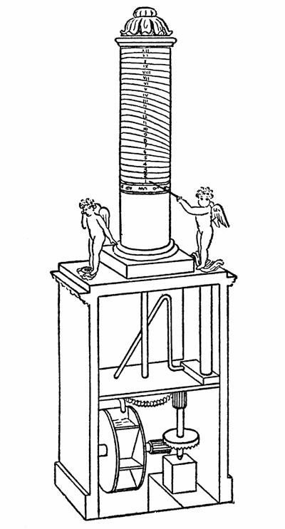
FIG. 25.—THE JEWELED WATER CLOCK BUILT BY CTESIBIUS ABOUT 250 B. C.
Figure 25 illustrates the most interesting clock he built and it was arranged to run year in and year out. The clock had a cylindrical face mounted on a hollow pedestal in which the mechanism was concealed. The column was divided off into twenty-four hours and a pointer that rose vertically marked off the lapse of time. But here he was faced with a serious complication. Hours in those days varied with the time of the year. A day from sunrise to sunset consisted of twelve hours. In summer, when the days were long, the hours were long, and in the short days of winter the hours were correspondingly shortened. To be sure, the variations in the length of the day are not so great in Egypt as they are in our latitude, because it is nearer to the equator; nevertheless there is a difference which the precise old mathematician had to take into account. In order to provide for variations in the hours, Ctesibius ran the lines spirally around the column and arranged his cylindrical clockface to turn slightly each day, so that in the winter months the clock hand or pointer moved over that part of the face where the daylight hour lines were closer together and the hours of night were farther apart, while in summer, the reverse would obtain. At the bottom of the column were two little cherubs. The cherub on the left was a sad little fellow who was constantly weeping. Tears trickled from his eyes and dropped into a basin. The tears passed into the hollow pedestal of the clock and gradually filled a cylinder formed in the base of the clock. A piston in this cylinder supported the other cherub. As the water gradually filled the cylinder this cherub was slowly raised and a wand he held in his hand pointed off the hours on the clockface. When the twenty-fourth hour was reached, a siphon came into play, which suddenly emptied the cylinder,[62] permitting the pointer to drop. The siphon discharged its water into a small water wheel, which, by means of the system of gears, turned the column slightly to bring the hour lines in proper positions for measuring the time intervals of the next day. The column made one complete turn in 365 days. The jeweled bearings, referred to above, were placed in the eyes of the weeping boy, so that the holes that pierced them would not be enlarged by the constant wear of the water and thereby increase the rate of flow.
TIMING ANCIENT ORATORS
We have dwelt at considerable length upon this old clock of the pre-Christian era to show the ingenuity of inventors of that day, and also the careful study that was made of time by ancient mathematicians and astronomers. Of course water clocks were used before the time of Ctesibius. In fact, we read of them in the comedies of Aristophanes, written 400 B. C. Water clocks were used to limit the long speeches of orators at court, and in one place we find Demosthenes accusing a man of “talking in my water,” while at another time, when he was interrupted, he called to the officer to stop the water, showing that he valued every moment of time allotted to him for his speech.
In 807 Charlemagne was presented with a clock by the King of Persia. This consisted of an elaborate mechanism in which were all manner of wheels, and the clock would actually strike the hours. The driving power, however, was water.
But there were serious disadvantages in the use of water for the measurement of time. No great accuracy was ever obtainable with it, owing to the[63] fact that its volume varied considerably with the temperature, and also with the dryness or moisture in the surrounding atmosphere. The idea of using a weight instead of water is claimed to have originated as far back as 990 A. D. The next important advance in the motive power of clocks was in 1500, when Peter Hele of Nuremberg invented the mainspring.
That was long before the pendulum made its appearance. The clock mechanism was slowed down and kept under control by what was known as a balance lever. (See Figure 26.) This was a horizontal lever mounted to oscillate in a horizontal plane. The lever was fitted with sliding weights, so that it could be carefully adjusted. The last wheel of the train of gears was provided with escapement teeth, somewhat similar to those used on our clocks and watches, but which would alternately move the lever this way and that. The inertia of the lever with the heavy weights on it was sufficient to prevent the mechanism from racing, and by this means, the motion was governed and slowed down, so that it measured time with a fair degree of accuracy.
DISCOVERY OF THE PENDULUM
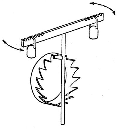
FIG. 26.—THE BALANCE LEVER, PREDECESSOR OF THE PENDULUM
The pendulum had an interesting origin. Galileo, while a student in Pisa in 1581, was attending a service in the cathedral one day when his attention was drawn to the swinging of a large hanging lamp. One of the attendants had drawn the lamp toward him, so that he could reach it more readily to light it. When he let go the lamp began to swing slowly back and forth, and the observant young student noticed that although the oscillations gradually slowed down the period of oscillation was constant. He had no watch with which to measure the length of the period, but being a medical student he knew that he had a fair timepiece in his own heartbeats, and so by counting his pulse he proved that it took the lamp just as long to complete each oscillation when it swept through a long arc as when it died down to but a few inches. He made note of this peculiar action and began experimenting with pendulums of different lengths. Then it occurred to him that if he could time the pendulum with his pulse he could time his pulse with a pendulum. So he devised a pendulum whose length could be adjusted until its oscillation would coincide with the throb of a patient’s pulse, and then the length of the pendulum would give him the rate of the pulse beat. The invention was seized upon by the medical profession of that day, and the pulsilogia, as it was called, became an indispensable instrument for physicians.
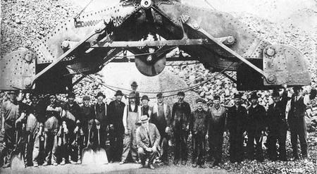
BUCKET OF A GIANT DREDGE WITH ITS JAWS SPREAD WIDE OPEN
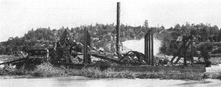
GOLD DREDGER EATING ITS WAY THROUGH RIVER SANDS

A SUCTION DREDGE EXCAVATING A CHANNEL AND BUILDING NEW LAND
The idea of using the pendulum to control the action of the clock also occurred to Galileo, and in later years, after he had lost his sight, he passed the idea down to his son, Vincent. However, it is generally conceded that the credit for introducing the pendulum and doing away with the balance lever belongs to Christian Huygens, the Dutch mathematician, whose first pendulum clock dates back to 1659.
About the same time Dr. Robert Hooke invented the balance spring which made it unnecessary to use the pendulum in portable timepieces. Prior to that watches were fitted with balance levers and they gave a great deal of trouble, because the time varied with the position in which they were carried. But the balance wheel overcame all these difficulties and made it possible for a person to carry an accurate timepiece in his vest pocket, although the early watches were very bulky mechanisms.
THE FIRST SHIP’S CHRONOMETER
The importance of having accurate timepieces aboard ship was felt as far back as the time of Columbus. When ships began to go out beyond the sight of land, it was highly important that they be equipped with some means of locating their position at sea. By noting the elevation of the sun at noon with a sextant it was possible to determine the latitude of the ship, but there was no means of determining its longitude, except by dead reckoning, that is, using a log to measure the speed of a ship, and[66] estimating its position by calculating the number of miles it had traveled since leaving port. If ships could be provided with an accurate timepiece which would keep the same time as that of some fixed observatory, it would be possible definitely to locate the position of the ship east or west by noting how fast or slow the sun was at noon on the particular day on which the observation was taken. This use of the chronometer is common in these days, but up to 150 years ago there was no timepiece sufficiently accurate to permit a navigator to tell with any certainty just where he was.
It was John Harrison, the son of a Yorkshire carpenter, who was the first to build a chronometer worthy of the name. A prize of 10,000 pounds was offered by the British Parliament for anyone who could invent and sell a chronometer which would enable a ship to take a voyage from England to any of the West Indian islands and back and keep track of the longitude within one degree. If this could be defined within two-thirds of a degree, the prize would be 15,000 pounds. Harrison made a bid for this prize, and after years of effort and patient labor, he succeeded in being granted a trial. His son, William, was sent on a ship to Jamaica with the now celebrated chronometer, which was mounted on a large cushion. The instrument was constantly attended by the young man, its position being adjusted from time to time to suit the “lie” of the ship. When the ship was eighteen days out, the vessel was estimated by dead reckoning to be 13° 50′ west of Portsmouth, but the chronometer indicated the position as 15° 19′. The timepiece was immediately condemned as worthless, but William Harrison had not lost faith in the instrument, and insisted that if[67] the ship continued on the same course, a certain island, if properly marked on the chart, would be seen the following day. True to the prediction, the next morning at seven o’clock the island appeared. By means of his chronometer William Harrison was able to predict the appearance of the other islands, and at the end of the voyage, which occupied sixty-one days, the chronometer was only nine seconds slow. When he returned to Portsmouth, after an absence of five months, the error of the chronometer was only one minute and five seconds, giving an error in distance of only eighteen miles, whereas thirty miles was the margin of error allowed by the prize conditions. Such accuracy seemed so incredible that the chronometer had to be tested on a second voyage, during which it was kept under lock and key and when William Harrison had to wind the instrument he was obliged to do so in the presence of two witnesses, lest he move the hand of the chronometer surreptitiously. At the end of the second voyage there was no further doubt that Harrison was fully entitled to the prize. Chronometers soon came to be used extensively, until now they are one of the most perfect of machines made by man, and operate with an accuracy that is almost incredible. Usually a ship is provided with several chronometers, so that one may be used as a check upon another. They are mounted in ball sockets and gimbal joints, so that they are not affected by the roll of the ship, but always lie in a horizontal position.
MARVELOUS PRECISION OF MODERN WATCHES
While we may well marvel at the precision of the chronometer, it is equally marvelous, if not more so, that we may equip ourselves for a few dollars with[68] a timepiece which is so wonderfully accurate as to vary little more than a second per day. If one took the pains to regulate his watch carefully, any of the better makes could be adjusted to such accuracy.
There is nothing very mysterious about the mechanism of a watch. It consists merely of a train of gears which slow down the motions of the mainspring to a convenient speed; and these gears moreover keep the proper relation between the hour and minute and second hands. But when we reflect that a small watch possesses a tiny second hand which travels something like ten miles in a year, and that if carefully regulated it will not vary from that of another watch in the whole journey by more than six or eight inches at the most, we certainly have a reason to marvel. There are 86,400 seconds in a day, and a watch is usually arranged to make five beats per second or 432,000 per day. The interval between beats must be adjusted with such minuteness that one beat must not differ from another by 1/86000 part of a second, else the watch will register more than a second fast or slow at the end of a day. And yet watches capable of such precision are being turned out daily by the thousands. Of course, such perfection would be absolutely impossible without the use of extremely accurate machine tools. It would have been impossible as long as we had to depend upon a watchmaker to make a watch by hand.
THE PACEMAKER OF A WATCH
If we look at the works of a clock the most conspicuous feature is the rapidly oscillating balance wheel which, by the way, is the most important part of the watch, for it governs the release of the power stored up in the spring.
It controls the escapement which brings the whole mechanism of the clock to a standstill five times each second—in fact it is the pacemaker of the watch, for it gives the watch a step-by-step movement and fixes the rate at which the steps are taken.
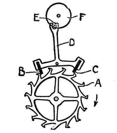
FIG. 27.—ESCAPEMENT OF A WATCH
The last wheel of the watch train is what is known as an escape wheel. It is formed with teeth of an odd shape, such as shown at A in Figure 27. These teeth are engaged by a pair of pallets B and C, carried by a three-armed lever D. The pallets are usually bits of sapphire or similar hard stone to prevent wear. The third of the lever is slotted at its extremity to engage a sapphire pin E, carried by a disk F, which is mounted on the staff of the balance wheel. The escape wheel A revolves in the direction of the arrow, being impelled by the mainspring acting through the train of gears. One of the teeth of this wheel engages the pallet B, causing the lever D to swing on its axis and push the[70] sapphire pin E toward the left, thereby giving the disk F an impulse in the same direction. Here a delicate coil spring, known as the hairspring, comes into play. Without the hairspring the parts would stand still, the escape wheel being blocked by the pallet B. The hairspring is attached at one end to the shaft or staff of the disk F and the other to the frame of the watch. It tries to hold the disk F in a fixed position, but is disturbed by the action of the escape wheel and is constantly oscillating the disk in its effort to bring it back to its normal position. When the disk swings over to the left the pallet B is clear of the teeth of the escape wheel. This releases the escape wheel and it springs forward in the direction of the arrow, but before it can move through an interval of one tooth it is arrested by the second pallet C, which has been projected into its path by the swing of the lever D. The lever swings back until the pallet C clears the escape wheel and the pallet B engages the next tooth. And so the action continues, the lever swinging back and forth and at each complete oscillation releasing one tooth of the escape wheel.
The hairspring takes up the shock of this intermittent motion and a balance wheel carried by the staff to which F is fastened steadies the oscillatory motion of the lever D. A watch is full of microscopic parts. In a small timepiece there are machine-made screws so small that without the aid of a magnifying glass one cannot see the screw threads cut upon them. But the most marvelous part of the whole watch is the delicate hairspring and the means of adjusting its tension and compensating for its expansion and contraction with changes of temperature.
INANIMATE MATTER IN CONTINUAL MOTION
When working with minute intervals of time many factors must be considered which are not even thought of in machines of grosser proportions. It never occurs to the man in the street that not only the animate world but the inanimate as well is in ceaseless and variable motion. If our eyes were capable of taking in minute microscopic details, we should see that everything is expanding or contracting, swelling or shriveling, twisting and warping in response to the atmospheric changes. Our steel bridges and skyscrapers are in constant motion; solid concrete dams must be provided with expansion joints; the Washington Monument goes through a diurnal gyration in response to the sun’s rays. Of course all this motion is almost immeasurably small. A bar of steel a mile long will expand ⅖ of an inch for every increase of a degree Fahrenheit in temperature. The expansion of a hairspring, which may be nine or ten inches long, is infinitesimally small and yet this must be considered by the watchmaker. We must remember that the escapement mechanism divides the day into 432,000 parts, each of which contains some minute error, for absolute perfection is impossible, and if we add up all these 432,000 errors they must not foot up to more than a second per day. If the hairspring expands ever so slightly its power is weakened, but this loss of power is compensated by an ingenious form of balance wheel. The rim is in two parts, half of it being attached to one spoke of the wheel and the other half to the other, as shown in Figure 28. Each half rim is formed of two strips of metal, an inner strip of steel, and an outer strip of brass[72] fused together. Brass expands and contracts almost twice as much as steel, and hence when there is a rise of temperature the rim sections tend to curl in, bringing their center of gravity nearer the center of the wheel and making less of a load for the weakened hairspring to move, while on the other hand, when the spring is contracted by cold, the rims spread out slightly, giving it a greater load to oscillate. The weight of the balance wheel is thus automatically adjusted against variations in power of the spring.
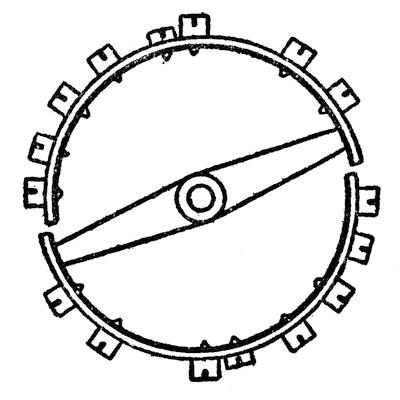
FIG. 28.—THE SELF-CORRECTING BALANCE WHEEL OF A WATCH
Aside from this automatic variable adjustment, the balance wheel must have a primary permanent adjustment. The rim of the wheel is loaded by means of small screws. Screws placed near the free ends of the rim sections will have a greater inward or outward play as the rim contracts and expands, and by their locations in different positions on the rims the balance wheel may be adjusted with great accuracy to compensate for temperature variation in the hairspring.
THE PENDULUM ESCAPEMENT
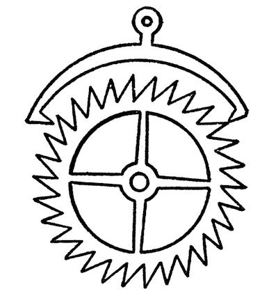
FIG. 29.—PENDULUM ESCAPEMENT
In the case of clocks such delicacy of adjustment is hardly necessary. Pendulum clocks, if they are to run accurately, must have their pendulums automatically adjustable for variations in temperature, because the longer the pendulum the more slowly it oscillates. Many years ago a grid type of pendulum was invented in which various alloys were used, which reacted one against the other and preserved the center of gravity always at the same distance from the center of oscillation. The action of a pendulum movement is similar to that of a balance-wheel movement described above. The pendulum operates a pallet lever similar to that shown in Figure 29. The teeth of an escape wheel, which are commonly somewhat different from those of the watch movement, strike the pallets of the pallet lever, and the escape wheel is intermittently stopped and permitted to proceed. The pressure of the escapement[74] teeth against the pallets is just enough to keep the pendulum swinging and the speed of the clock is regulated by lengthening or shortening the pendulum.
We have added little to clock or watch movements in recent years. About the only conspicuous modern invention is the torsion pendulum. The pendulum in this case is a heavy horizontal disk suspended by a wire, and the disk rotates first in one direction and then in the other, twisting and untwisting the wire. The advantage of this pendulum is that the oscillations are very slow, and hence it is possible to keep the clock going for a year at a single winding.
The electric regulation of clocks is another important improvement. A clock need not be a very perfect timepiece, but if provided with an electric regulator its hands are brought up to the correct time every hour in response to an impulse sent from an accurate master clock which in turn has its time corrected daily from the National Observatory in Washington.
CHAPTER V
PUTTING RIVERS TO WORK
FLOWING water exerts a strange fascination upon mankind, even to the present day. Tourists travel hundreds of miles to view the glorious spectacle of a riotous tumbling cataract. Is it strange, then, that in the olden times, when the world was peopled with gods and genii and strange spirits, the ancients looked upon ceaselessly flowing rivers as the symbol of life? It was most natural for them to covet the endless power of a river and eventually, despite their superstitions, to try to utilize some of its energy.
It may be that sailboats antedate the first water wheel, but it seems much more probable that flowing water was the first inanimate power harnessed by man. Windmills were certainly a later development. They possessed the advantage that they could be located anywhere while the water mill had of necessity to be built along the bank of a stream. However, the power of the wind is so unreliable and fluctuates so widely that it was little used, except in flat countries, where there was little if any available water power.
Water power predominated until the steam engine was introduced, when it had to give way to an even more reliable power and one which could be located at any place to which fuel could be transported. Now, however, we are going back to our first power,[76] seeking it out in the most inaccessible mountainous regions, because we have discovered the means of taking the power it yields and transmitting it hundreds of miles, over hills and plains to the point where we can put it to useful service. Hydroelectric power has very aptly been termed “white coal.”
The first prime motor was the current wheel, that is, a wheel fitted with paddles, which was journaled over a stream with the paddles projecting into the water. This was a very inefficient machine; it converted very little of the energy of a stream into useful mechanical power. The idea of damming the stream and letting the waters flow over the dam through a raceway upon a water wheel was a much later development.
WATER WHEELS
Three types of water wheel which were in universal use before the advent of the steam engine were the undershot wheel, the overshot wheel, and the breast wheel (Figure 30). In the undershot wheel the water stored back of a dam is let out near the bottom of the dam and strikes the under side of the wheel, so that the top of the wheel turns toward the dam. In the overshot wheel, the water flows over the wheel striking the paddles or buckets on top and on the forward side, so that the wheel turns forward. In the breast wheel, the water strikes the paddles half way up the wheel on the rear side and drives the wheel in the same direction as that of the undershot wheel.
When we speak of water power we are apt to think of the water as actually furnishing the energy. As a matter of fact, it is not water but gravity that drives the wheel, the water being merely the medium[77] that gravity acts upon. By having the water drop from a great height, its velocity is greatly increased and the power it imparts to the wheel is much higher. In mountainous regions it is easy to obtain a high head of water and thus generate a great deal of power from a relatively small stream. However, the ancient type of wheel with its paddles or buckets has now practically passed out of existence, being superseded by the Pelton wheel for high heads and the turbine for low heads of water.

FIG. 30.—UNDERSHOT, OVERSHOT, AND BREAST WHEELS
INVENTION OF THE PELTON WHEEL
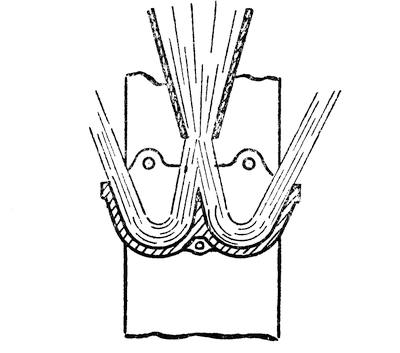
FIG. 31.—SECTIONAL VIEW OF A PAIR OF PELTON WHEEL BUCKETS SHOWING HOW THE WATER JET IS DIVIDED AND FOLLOWS THE CONTOUR OF THE BUCKETS
In California, a number of years ago, they made use of what was known as the hurdy-gurdy wheel. This consisted of an ordinary wheel with bucket-shaped paddles against which was directed a stream of water at high velocity through a nozzle. There was a carpenter, named L. A. Pelton, who used to make a business of building and repairing such wheels and the flumes that carried the water to them. Although uneducated, he was possessed of considerable native ingenuity and was a very observant man. One day, when he was called in to repair a wheel, he noticed that one of the buckets which had been misplaced received the water from the nozzle without any splashing. The water struck the edge of the bucket with practically no shock, whereas the other buckets produced a great deal of splashing. Pelton had enough knowledge of the principles of mechanics to realize that a splash means a waste of energy, and that here was a bucket which, although out of plumb and apparently defective, was really more efficient than any of the others in the wheel. It occurred to him then that instead of having the jet of water strike the middle of the buckets it ought to strike the edge, so that all its power would be absorbed without any wasteful splashing. He might have displaced the jet laterally so as to accomplish this result, but he realized that that would have produced a considerable side thrust on the wheel, which, of course, would have been objectionable, and so he hit upon the plan of using double buckets and letting the stream of water strike the pair of buckets along their dividing line.[79] (See Figure 31.) This would split the stream in two and let each half strike the slanting face of the bucket, and follow the surface around in the same way that it did on the single misplaced bucket, but the reaction or side thrust on one bucket would be counteracted by that on the other. This idea proved successful and out of it has grown the Pelton wheel which is now universally used in all power plants employing high heads of water.
A 4,000-FOOT HEAD OF WATER
A notable illustration of such a plant is the great installation at Big Creek, Cal. Big Creek, despite its name, used to be a small stream flowing down the mountains into a canyon. One would hardly suppose that it was capable of yielding much power, but it had its source high up in the Sierras and was fed mainly by melting snows. In the springtime, it swelled to a good-sized torrent. By building three dams near the top of the mountain, a lake was formed in which the water of the melting snow was impounded, so that a steady stream of water could be supplied the year round for power purposes. But even so, the stream hardly amounts to very much if we consider only the quantity of water that passes through it. The particular advantage of this installation is the fact that in a distance of six miles from the dam the creek falls 4,000 feet.
An inhabitant of the Eastern States who is unused to mountain heights may gain some conception of the meaning of this elevation by gazing up to the pinnacle of the Woolworth Tower, which rises 795 feet above street level, then mentally multiplying its altitude by five. Evidently even a small stream of water dropping from such an elevation would develop[80] an enormous amount of power. In fact, it was considered inexpedient to use the entire fall at a single drop and so it was divided into two stages. The water is carried through a tunnel three-quarters of a mile long and then through a flow pipe along the face of the mountain to a point where it may drop 2,000 feet to the first power plant. After passing through this plant the water is discharged into the creek and is then diverted into a second tunnel four miles long and a series of steel conduits to a point from which it may drop 2,000 feet more to the second power plant. In each power house there are two electric generators, each fitted with a pair of Pelton wheels. These wheels are a little less than eight feet in diameter and each one develops 23,000 horsepower.
The water is directed into the buckets of the Pelton wheel in a stream six inches in diameter, and it issues from the nozzle with a velocity of 300 feet per second or about 210 miles per hour. A jet of water is almost like a solid bar of wood. In fact, it is impossible to chop through it with an ax. The water would swing the ax out of one’s hand before it got part way through the jet. Traveling at such a high speed the friction is so great that it would tear the skin off one’s hands, if it did not actually tear the hand off the arm, and yet it strikes the buckets of the wheels with no shock at all, for the first part of the bucket it touches is nearly parallel to the jet, and as the water sweeps around the curved face of the bucket it loses practically all of its pressure and velocity and falls into the tail race. The electric power generated by the two plants is stepped up to 150,000 volts and sent out over transmission lines to points of service. The street cars[81] of Los Angeles are connected by a 240-mile electric harness to the hydraulic horses of Big Creek.
Powerful as this stream is, a still higher head is used in Switzerland, at Lake Fully, where there is a drop of over a mile in a distance of 2.8 miles. The water is carried by a short tunnel through the mountain, and then makes a drop of over 5,000 feet to the power plant, where it strikes the Pelton wheels at a velocity of 400 miles per hour, or about seven times the speed of a fast express train.
HARNESSING THE MISSISSIPPI
In contrast to such high heads, we have the low-head power plants which are employed where a large volume of water is available. The most notable installation of this type, and the largest in the world, is that at Keokuk, Iowa, where a dam has been thrown across the Mississippi River. For many years it was thought impossible to make any use of the vast volume of water that flows through this great river. But above Keokuk there used to be a rapid extending back about twelve miles. By building a dam across the river just below the rapid it was possible to obtain a working head of about thirty-two feet, and with the enormous volume of water available this provided sufficient energy to make the development worth while. In marked contrast to the installation at Big Creek, it is volume rather than velocity that is employed, and hence turbines rather than Pelton wheels are used. More water goes through a single turbine than is used in the whole of the city of New York with all its elaborate aqueduct system. Enormous turbines are used, fifteen feet in diameter, and when the installation is complete there will be thirty units,[82] each yielding 10,000 horsepower, or a total of 300,000 horsepower. A turbine, it may be explained, differs from the ordinary water wheel in the fact that the water runs through the wheel instead of around it (Figure 32). The water may enter at the center and then flow out at the periphery, or it may enter at the periphery and then be discharged from the center of the wheel, or it may run axially through the wheel. In a Pelton wheel there is a single jet which strikes but one pair of buckets at a time, but in a turbine there are many jets distributed all around the circumference of the wheel. The water is divided into a series of jets by being forced through a stationary set of curved vanes. The blades of the rotor or revolving part of the turbine are oppositely curved. If the rotor were immovable the jets would have to change their direction in passing through the rotor, but as the rotor is free to turn, the jets react against these blades and set the wheel to revolving. The turbine may be designed to run either on a horizontal axis or on a vertical one.
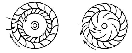
FIG. 32.—TURBINE WHEELS; INFLOW TYPE SHOWN ON THE LEFT AND OUTFLOW TYPE ON THE RIGHT
The turbines used at the Keokuk plant are of the inflow type. The rotor is mounted on a vertical shaft in a scroll-shaped concrete chamber, something like[83] a snail shell. Water pouring into this chamber is thus given a swirling motion in the direction of rotation of the wheel. As it flows into the wheel it passes first through a ring of fixed vanes, which divide it into the jets.
The highest velocity of a wheel is naturally at the periphery and the advantage of an inflowing turbine such as this is that the water is traveling at its highest velocity when it strikes the periphery of the rotor. As it loses its velocity it flows in toward the slower-moving portions of the rotor. Finally it reaches the center, after giving up practically all its energy, and falls into the tail pool through a draft tube at the center of the rotor.
The scroll chambers at Keokuk are thirty-nine feet in diameter and the draft tubes are eighteen feet in diameter. Water enters the scroll chambers with a velocity of fourteen feet per second and comes out of the draft tubes into the tail pool with its velocity cut down to but four feet per second. Compare this with the velocity of the water jets at Big Creek!
The current generated at Keokuk goes to St. Louis and surrounding towns and serves a population of 1,120,000.
Now that we have learned how to transmit electrical power without serious loss over enormous distances, it is only a question of time before all the water power in the world is harnessed and put to the service of man. The power costs nothing after once the plant has been built; the only expense is that of maintaining the machinery and keeping it in repair. It is estimated that there is some 200,000,000 horsepower available in this country, but this includes all flowing water, much of which it[84] would be impracticable, if not almost impossible, to utilize. However, there is about 60,000,000 horsepower commercially available, according to the figures of the U. S. Geological Survey, of which we have developed so far only 6,000,000 horsepower.
The ancients used flowing streams not so much for power purposes as to lift water to a higher level so that it would flow into their irrigating ditches. Nowadays, electricity, steam, or air is used for elevating water, but we have a very ingenious machine which makes the stream lift a part of itself. This machine is very different in principle from the old Egyptian noria. It depends upon the kinetic energy of water in motion. You cannot push a nail into a piece of wood with a hammer but you can easily drive it in by striking it with the hammer. As the hammer is swung it acquires what we term kinetic energy or energy of motion.
SETTING KITCHEN FAUCETS TO WORK
It is not generally realized that water in motion also acquires kinetic energy. Whenever a faucet is turned off very quickly, there is a hammering sound which is due to the fact that the moving water in the water pipe is brought to an abrupt stop. This puts a severe strain on the piping. A great deal of trouble was experienced from this source in the early days of plumbing. At a hospital in Bristol, England, there was a lead pipe leading from a cistern in one of the upper stories to the kitchen. Every time the faucets were turned off abruptly the momentum of the water caused the lead pipe to expand, and every now and then the pipe was burst. In order to relieve the situation, a plumber connected a pipe to the faucet and carried it up the side[85] of the building to the level of the cistern. His idea was that whenever the water was turned off suddenly it would have a vent leading up to the level of the water reservoir. Much to his surprise, the water issued from the pipe in a jet of considerable height. To prevent the escape of the water, he extended the pipe considerably, and still a jet of water would issue from it. Eventually the relief pipe was carried up twice the height of the cistern and even then the water would squirt out occasionally when the faucets in the kitchen were turned off very suddenly. Then the idea was conceived of placing a reservoir on one of the upper floors of the hospital and letting the jet of water fill this reservoir. Every time the faucet was operated in the kitchen a certain amount of water flowed into the new cistern, and in this way it was kept supplied with enough water to furnish that which was required for the upper floors of the hospital.
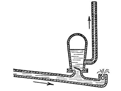
FIG. 33.—SECTIONAL VIEW OF A WATER RAM
It is on this principle that the hydraulic ram operates. Water from a stream is made to flow down a pipe, and as it gains velocity a check valve suddenly[86] stops the flow which produces enough pressure to force open a valve in an air chamber and let some of the water enter the chamber. As soon as the pressure is relieved the check valve opens and the valve into the chamber closes automatically until a moment later the stream of water has gained sufficient velocity to repeat the performance. Thus an intermittent jet of water is forced into the air chamber and thence through a pipe to a reservoir. The height to which the water will rise depends entirely upon the velocity of the water flowing through the system. The air chamber is necessary to cushion the action of the hydraulic ram and provide a fairly steady pressure upon the water that flows up through the vent pipe. The check valve is entirely automatic. It is held open against the pressure of the water by a spring or a weight, but when the water is in motion is dragged shut, only to spring open again when the pressure is reduced by the escape of the water into the air chamber.
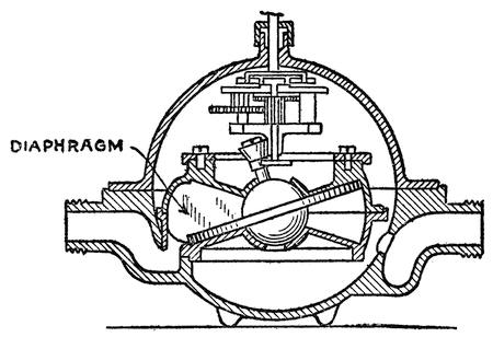
FIG. 34.—THE GYRATING WATER METER
There is a very ingenious water-driven motor which is employed merely to record the amount of water flowing through it. This is the Thomson water meter which is illustrated in Figure 34. It consists of a circular chamber with inwardly dished or conical top and bottom walls. In the chamber is a flat disk with a ball and socket bearing. At one side there is a vertical diaphragm in the chamber which passes through a slot in the disk. This prevents the disk from revolving, but it is free to oscillate. It has a motion similar to the gyrations of a top when it is beginning to lose speed and die down, except that the disk does not revolve. When the disk is in contact with the bottom wall of the chamber on one side it contacts with the top wall on the other so that the chamber is virtually divided into two compartments by the disk, but by gyrating the disk these compartments are made to revolve. Water enters at one side and discharges at the other side of the vertical diaphragm. Now, if the disk is in the position shown in Figure 34, the water, on entering, bears upon the upper face of the inclined disk and wedges its way between the disk and the upper wall of the chamber, making the disk oscillate on its ball center. As the edge of the disk rises across the face of inlet port the water entering the chamber bears against the under side of the disk, continuing the gyratory motion. The water cut off on the upper side of the disk is carried around to the outlet and discharges, while a fresh supply flows in on the other side of the vertical partition and at the next half turn the water in the lower compartment discharges at the outlet side of the partition, while the compartment is filling on the other side of the partition. A measured amount of water flows through[88] the chamber at each gyratory oscillation of the disk. A train of gearing is driven by the gyrating disk which operates a set of dial pointers and a measure of the amount of water passing through the meter is indicated.
DIGGING WITH WATER JETS
We have referred to the enormous velocity of the jets used to drive Pelton wheels. Where high heads of water are obtainable water jets are used very effectively for excavating purposes, particularly in mining plants for washing down gold-bearing gravel banks. If water is not found near such banks expensive canals, flumes, and pipe lines are constructed and even tunnels are bored to bring the water to the point where it can be utilized. Some of the giant nozzles spout streams from 2 to 8 inches in diameter with a pressure of from 50 to 200 pounds per square inch. The powerful streams tear into the gravel banks, washing them away into sluices in which riffle boxes are placed to catch the precious metal. The back pressure of these nozzles is very heavy and the larger ones have to be provided with strong anchorages. Water in motion resists any change of direction and long levers have to be provided to permit the miners to guide the nozzles.
The hydraulic jet is also used for general excavating wherever water power is available. Sometimes it is employed under water when clearing a channel to level down piles of stones that are too large to be picked up by a suction dredge. Hollow iron piles are driven into a sandy bottom by means of hydraulic jets. No hammer is needed. Water is pumped into the pile and on issuing from the bottom[89] of the pile it carries sand with it, making a hole into which the pile sinks. Wooden piles are driven in the same way by loosely attaching a water pipe to them so that the pipe may be withdrawn when the pile has been driven far enough. The pile is grooved at the lower end so that the pipe outlet may be centered at the bottom of the pile.
COMPRESSING AIR WITH WATER
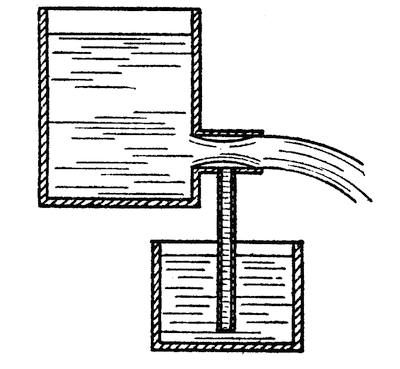
FIG. 35.—HOW THE VENA CONTRACTA RAISES WATER
A very ingenious apparatus for compressing air was invented in the earliest years of the iron age to furnish a continuous blast of air for the Catalan forges. This compressor, known as a “trompe,” can hardly be termed a machine because it contains no moving parts except water, which is the motive power, and the air which it traps and compresses. To understand its operation we must look into a peculiar property of water flowing out of a reservoir into a pipe or nozzle. There is a converging motion that tends to contract the jet of water just after it leaves the pipe. This is known as the vena[90] contracta. It produces a partial vacuum in the pipe. If air ports are opened into the pipe at this point, air will be sucked in to fill the vacuum and will be carried out of the pipe by the friction of the water. In Figure 35 a pipe is shown running from the vena contracta to a water tank below. The rise of water in this pipe indicates the degree of vacuum produced by the jet.
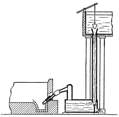
FIG. 36.—THE “TROMPE” BY WHICH COMPRESSED AIR WAS FURNISHED FOR CATALAN FORGES
This principle is used in the hydraulic-air compressor or “trompe” as it is called. Water flows out of one reservoir through a pipe into another reservoir lower down. (See Figure 36.) Air enters[91] the pipe through ports at the point where the vein of water contracts and is carried down into the second reservoir. This reservoir is sealed so that the air is trapped in it. The water passes out through a pipe which is carried high enough to keep a certain pressure of air in the reservoir and prevent it from blowing out.
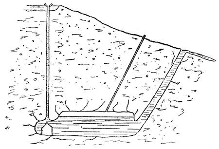
FIG. 37.—DIAGRAMMATIC SECTION OF A LARGE HYDRAULIC AIR COMPRESSOR IN MICHIGAN
There is a compressor of this type, constructed on an enormous scale, in the northern part of Michigan. A sketch of the compressor is given in Figure 37. The air reservoir in this case is a huge underground rock-walled chamber nearly 350 feet below the surface, 8 feet wide, 26 feet high, and about 280 feet long. There are three intake pipes, 5 feet in diameter, each filled with an annular funnel-shaped head, which sucks air into the water and carries it down into the chamber. At the bottom of each intake pipe there is a concrete block with a conical top projecting up into the pipe. The column of water flowing[92] down the pipe is spread out into an annular stream by the conical block and the bubbles of air escape into the chamber. The water outlet of the chamber is an inclined shaft which leads up about 270 feet to the surface of the ground where it discharges into the tail race. The water is forced up this inclined shaft by the pressure of the air trapped in the chamber. The mouth of the shaft is, of course, below the level of the water in the chamber so that there is no chance for the air to escape unless the pressure becomes excessively high, when it will force the water level below the mouth of the shaft and blow out. The discharge sometimes forms a geyser 700 feet high. The air will continue to blow until the pressure is reduced enough for the water level to rise and cut off access of the air to the mouth of the shaft. Under normal conditions there is a fall of 343 feet from the water level at the top of the intake pipe to the water level in the chamber, and a vertical rise of 271 feet from the water level in the chamber to the tail-water level. The difference, or 72 feet, represents the working head. With all three intakes operating, a total of 5,000 horsepower is developed. Each intake delivers 11,930 cubic feet of air per minute at a pressure of 128 pounds. Air enters the intake heads through tubes ⅜ inch in diameter and there are 1,800 of them to each head. The air is employed to operate machinery and tools in an adjacent mine.
One advantage of this type of air compressor is that it cools the air while compressing it. This was hardly an advantage in the Catalan forges, but when the air is used to drive machinery it is important that it be precooled. When air is compressed by mechanical means a great deal of heat[93] is generated and the machines must be water jacketed to extract this heat, but in the hydraulic compressor the air bubbles are compressed as they pass down with the water to the reservoir and the water absorbs the heat, delivering cool compressed air at the bottom of the intake pipe.
CHAPTER VI
LIQUID LEVERS AND GEARS
MANY an inventor has strayed off into the delusive pursuit of perpetual motion because he did not know that the pressure in a body of water at any given point is equal in all directions, upward, downward, or laterally.
A cubic foot of water weighs 62½ pounds. Take a hollow column with an internal cross-sectional area of one square foot and if it be filled with water to a depth of ten feet there will be a weight of 625 pounds of water in the column and hence a pressure of 625 on the bottom of the tube or 4.34 pounds on every square inch of the bottom. But the water presses on the sides of the tube as well and the amount of this pressure depends upon the depth or “head” of water and not upon the quantity of water. At the bottom of the tube the pressure on the side walls is 625 pounds per square foot or 4.34 pounds per square inch; at a depth of one foot the pressure on the side walls is 62.5 pounds per square foot or .434 pound per square inch; at a depth of two feet it will be .864 pound per square inch, etc. The pressure on each square inch depends not upon the mass of the water but upon its depth. If the column of water had a cross-sectional area of a mile or a thousand miles, the pressure at a depth of one foot would always be .434 pound per square inch. (Of course there are slight variations from this figure due to salt or other substances dissolved in water[95] or to changes in density produced by variations of temperature, but we need not consider such minute differences here.) That is why a dam which is strong enough to hold back the waters of a pond will be just as able to hold back the waters of the whole ocean if it be placed in a sheltered bay where ocean waves cannot tear it to pieces. The ocean, despite its enormous mass, can exert no more pressure per foot of depth than the water in a cistern.
WHY A SHIP FLOATS
It is because the pressure of water at a given depth is exerted upward, as well as laterally and downward, that a ship floats. It is the upward pressure of the water that holds up the boat. When an object is placed in a reservoir of water it sinks into zones of increasing pressure until it finally reaches a depth at which the pressure on the bottom of the object balances the weight of the body. If the body is entirely submerged before reaching such a point, it will continue to sink to the bottom of the reservoir because water will flow over the top of the object and keep adding downward pressure to offset the increasing upward pressure. The amount of water in the reservoir makes no difference. A battleship will float just as high in a flooded dry dock as it will in the open ocean. If the dry dock were so narrow as to leave a clearance of but a few inches of water around the ship, the latter would still float even though the ship weighed considerably more than the water in the dock.
There is a big difference, then, between the weight of water and the pressure it exerts. In Figure 38 we have an L-shaped receptacle with the lower arm of the L terminating in a chamber A. The top wall[96] B of this chamber measures ten square inches. The tube C has a cross sectional area of one square inch. If tube C is filled to a height of twelve inches above wall B we shall have an upward pressure of 0.434 pound on every square inch of wall B, or a total of 4.34 pounds. If by means of a plunger D we add a hundred pounds of pressure to the column of water in tube C, we shall be adding a thousand pounds to the pressure on the wall B. The side walls and bottom of the chamber A will also be subjected to a pressure of 1,000 pounds per inch plus the pressure due to the depth or head of water.
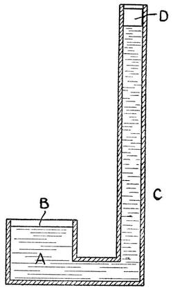
FIG. 38.—DIAGRAM ILLUSTRATING HYDROSTATIC PRESSURE
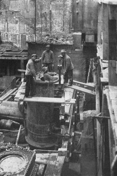
THE AIR-LOCK OF A PNEUMATIC CAISSON
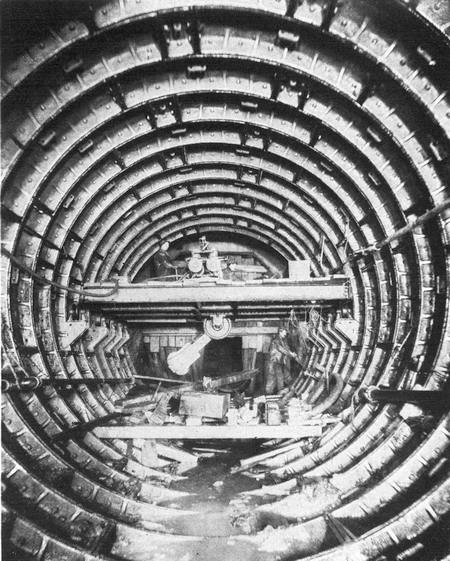
SUBAQUEOUS TUNNEL, SHOWING THE SHIELD IN THE BACKGROUND
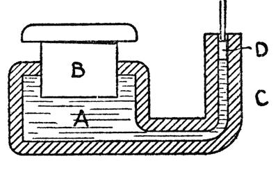
FIG. 39.—PRINCIPLE OF THE HYDRAULIC PRESS
Here, then, we have a convenient means of multiplying force or effort and it is a means that is used very largely in certain classes of machinery. Figure 39 is a diagrammatic representation of a hydraulic press. It consists of a cylinder A in which is fitted a ram B. An L-shaped tube C connects with the cylinder and is fitted with a plunger D. The cylinder and tube are filled with water and then when the plunger is depressed the ram B has to rise, If the area of the plunger is one square inch and that of the ram thirty square inches, a 100 pounds pressure on the plunger will exert 3,000 pounds of lift on the ram.
HYDRAULIC LEVERAGE
However, we must remember that in mechanics, as in all walks of life, we cannot get “something for nothing.” If we multiply the pressure or force, we must pay for it in some way, otherwise we should be getting more work out of the press than we put in it, which is what the perpetual motion crank is ever trying to do. As the cross-sectional area of the plunger D is only 1/30th of that of the ram, the plunger must descend thirty inches to raise the ram one inch. We need not consider the difference in the head of water because it would not amount to[98] more than a few ounces at most, nor need we consider frictional losses. The case is parallel to that of the lever. In fact, we may consider the hydraulic press as a fluid lever with the water in tube C as the effort arm and that in cylinder A as the weight arm. The two arms are here so proportioned that the power arm must move thirty times as far as the weight arm. The work put into the press is exactly balanced by that we get out of it. An effort of 100 pounds exerted through a distance of thirty inches is exactly balanced by the moving of 3,000 pounds through a distance of one inch.
It is a decided disadvantage to have to move the plunger so far and in actual commercial practice hand-operated hydraulic presses are not worked in that way. A pump is used to force water into the cylinder so that a great many short strokes may be taken in place of one long one, and the pump handle provides an added leverage, enabling a man with little effort to exert an enormous lift. The water enters the ram cylinder through a valve, and the pressure is maintained on the ram until relieved by the opening of an outlet port.
MAUDSLEY’S LEATHER COLLAR
All this seems very simple and one would suppose that the inventor of the hydraulic press must have been exceptionally free from the troubles and trials that beset most inventors. However, there is a vast difference between a laboratory apparatus and a commercial machine. When, towards the close of the eighteenth century, Joseph Bramah, the eminent British tool builder, invented the hydraulic press, he experienced all sorts of difficulty in holding the water in the ram cylinder. Of course, the ram has[99] to slide freely into and out of the cylinder, but how could he prevent the water from leaking out past the ram? He resorted to all the plumbing expedients of the day. He used a stuffing box and gland, but when this was packed tight enough to hold the water in, it gripped the ram so tightly that the latter would not move down into the cylinder on the return stroke. Bramah had in his employ a very clever young mechanic named Henry Maudsley, who later became famous as an inventor and designer of machine tools. We read of him in Chapter III. Maudsley attacked the baffling problem of the hydraulic press and provided a solution that survives to this day. In place of the stuffing box which is a means of jamming a mass of cotton waste about the collar, he provided a cupped leather collar. When the pressure was applied it expanded the collar and made it bear tightly against the ram, but on relieving the hydraulic pressure the pressure of the cup leather was also reduced automatically.
There are many machines analogous to the hydraulic press in principle. They do not use water in every case for the fluid lever. Where the fluid is used over and over again oil is frequently employed. The compactness of this form of lever makes it most useful wherever an operation calls for the overcoming of a very heavy load or resistance through a relatively short distance. For instance, there are machines for bending pipe, for curving railroad rails, for punching holes in metal, for pulling wheels off their shafts, for jacking up heavy weights, for baling cotton, paper, and other materials, all of which operate on the same principle as the hydraulic press. Water pressure is supplied sometimes by a hand pump, sometimes by a[100] power-driven pump, and sometimes it is taken from a reservoir in which compressed air imparts the requisite pressure to the water.
BLASTING WITH WATER
A novel use of water pressure has been developed in England. In certain mines it is dangerous to use dynamite for blasting purposes owing to the presence of explosive gases, and successful experiments have been made with hydraulic cartridges. This consists of a cylinder of steel fitted with a series of little plungers arranged in a row in the cylindrical wall of the cartridge. As in powder blasting, a series of holes are drilled in the face of the rock and the cartridges with the plungers retracted are fitted into the holes. Then the cartridges are connected to a high-pressure water supply. The water forces the plungers out, exerting enough pressure to burst the rock. Not only is this system perfectly safe, but it is economical, because the gallery does not have to be cleared of workmen before every blast. There is more certainty in the use of water cartridges, and the danger, common where dynamite is used, of having the rock drill or pick strike and explode a stick of dynamite which failed to go off with the rest of the charge in a previous blast is avoided.
Hydraulic pressure is also used in jacks for lifting heavy weights. The principle of the hydraulic jack is the same as that of the hydraulic press.
RAISING A BRIDGE SPAN WITH WATER
An interesting illustration of the use of these liquid levers was afforded in the construction of the Quebec Bridge. This huge bridge, it will be recalled,[101] consists of two cantilevers which stretch out from opposite shores of the St. Lawrence River and support between them a center span 640 feet long and weighing 5,400 tons. The span was built on barges, towed down to position between the cantilever arms and then lifted up 150 feet to the floor level of the bridge. Eight 1,000-ton hydraulic lifting jacks were used, two at each corner of the span. They were ideally suited to this kind of work. The bridge span had to be lifted with utmost care and the motion had to be simultaneous on all four corners. If one corner were raised faster than another the span would be twisted and subjected to serious strains. In the first attempt the fastening gave way at one corner and the span crumpled up and plunged down into the river. But a year later at the second attempt the span was hoisted successfully to position. The jacks had a lift of two feet, and, counting the time required to secure the huge plate chains by which the span was suspended, move the jacks down and give them a fresh hold, it took fourteen minutes to complete each two-foot lift. The work was done only during the daylight hours and on the third day the span was finally brought into position and made fast to the cantilever arms by means of twelve-inch pins driven home at each corner.
Hydraulic power is used very largely in the operation of cranes. As the plunger or ram has a very limited range of motion some means of multiplying distance of travel is required. One simple scheme is to use a set of pulley wheels or sheaves attached to the cylinder and another set to the ram and pass the hoisting chain around them. If we refer back to Figure 16, on page 34, we shall see that seven feet of rope must be pulled in at E in order to raise the[102] lower pulley block one foot. It is very evident that the process can be reversed. Power might be applied to spread the two-pulley blocks apart when a movement of one foot would produce a travel of seven feet at E. That is what is done on the hydraulic crane. The ram is lifted, spreading the pulley blocks apart and thus multiplying the motion of the lifting cable to any extent, depending upon the number of sheaves, so that a travel of but a few feet will result in lifting a load forty or fifty feet.
HYDRAULIC ELEVATORS
The same principle is used in hydraulic elevators. The hydraulic cylinder lies horizontally on the basement floor and by means of pulley gearing a short motion of the plunger is sufficient to raise the car several stories.
In a more modern type of elevator the plunger acts directly on the car. The plunger is long enough to reach to the top story of the building which means that it must sink far into the ground in order to let the car down to the first story or basement. A steel pipe is sunk into the ground and serves as the cylinder and in this the long plunger operates. In one of New York’s tall buildings the cars are lifted to a height of 282 feet. The plungers are 6½ inches in diameter and they travel at a speed of over 400 feet per minute. The car which, when loaded, weighs 1,617 pounds, is supported on the top of the plunger. However, counterweights are provided which balance the weight of the car, so that practically the only weight lifted by the plunger is that of the passengers. The advantage of this type of elevator is that it reduces the danger of accident. The motion of the car is steady and easily controlled.[103] The car cannot move down above a given speed and the only possible danger is that the plunger might break. However, a shaft of steel 6½ inches in diameter, even if hollow, is hardly likely to give way even under the most extraordinary loads to which it might be subjected in elevator service.
LIFT LOCKS FOR CANALS
There is another type of elevator that completely dwarfs anything used in office buildings. On some canals where it is necessary to make a sudden change of level of considerable extent, instead of using a flight of locks, a hydraulic elevator is employed to lift or lower not only the vessel but the water it is floated in. There are two huge tanks which ply between the upper and lower levels of the canal. These are so connected that as one rises the other descends. The tanks are big enough to take in the largest vessels that are likely to use the canal. They are fitted with water-tight gates at each end, and after a vessel has entered one of them, say at the lower level, the gate behind it is closed. Then hydraulic mechanism is operated to lift the tank, and when the top is reached the other gate is opened and the vessel sails out into the upper level. It seems like a tremendous undertaking to lift a heavy ship, but the two tanks balance each other and the only work that has to be done is to overcome the friction and inertia. No matter how heavy a vessel may be, it will not disturb the balance between the two tanks. Nor is it necessary to have a ship in each tank, for the same depth of water is maintained in the two tanks, and when a ship enters the weight of the tank is not increased, for the ship displaces its own weight of water.
HYDRAULIC VARIABLE SPEED GEAR
Water is frequently used to take the place of toothed gearing for the transmission of power, particularly where it is desirable to vary speed. One of the disadvantages of toothed gearing is that a change of speed can only be made by shifting gears. The speed cannot be varied gradually but is changed by abrupt steps. The guns of a battleship must be kept trained on the target, while the ship rolls in the waves under them, so as to be ready for a broadside at any instant. A telescope is secured to the barrel of the gun and a man known as a “pointer” tries to keep the cross-hairs of a telescope on the target by constantly elevating or depressing the gun. The speed of the elevating machinery must be constantly changing; now running at high speed, the next instant barely moving, and the next moment reversing.
To produce these variations a hydraulic variable speed gear is used. The construction is somewhat complicated, but the general principle of operation is simple. In a common pump water is lifted by operating a plunger in and out of a cylinder. It will be readily understood that the operation may be reversed, and if power is applied to the water to force it through the pump, it will make the plungers move in and out of the cylinder. In the hydraulic variable speed gear the driving shaft is made to operate a set of little pumps which are connected to a second series of pumps that act upon the driven shaft. Instead of water oil is used, and the oil pumped by the driving pumps is forced into the driven pumps. The latter pumps are so connected to the driven shaft as to cause it to rotate. But by[105] a simple mechanical expedient the stroke of the driving pumps can be varied at will from maximum to zero, and the motion of the pumps can also be reversed. The variable amount of oil pumped into the driven pumps varies the speed of the driven shaft, for if it takes two strokes of a driving pump to fill the cylinder of a driven pump the driven shaft will travel at only half the speed of the driving shaft.
In turbine-driven vessels some sort of gearing is required between the propeller and the turbine. In order to operate at its best efficiency a turbine must run at very high speed, but this speed is entirely too high for the propeller. There is a limit to the rate at which a propeller may be driven. If this limit is exceeded, the propeller merely bores a hole in the water, forming a vacuum which produces a drag on the ship. It is customary to interpose some form of gearing between the propeller and the turbine shaft, but because of the high speed and the vast amount of power to be transmitted it is a difficult matter to design gearing that will be reliable. Furthermore, it is desirable to vary the speed of the vessel and even to reverse it without slowing down the turbine engine. In some cases a specially designed system of toothed gearing has been employed, in another the power of the turbine is converted into electricity and then reconverted into mechanical power by means of a motor on the propeller shaft. This provides a very efficient transmission, because the electricity can be very conveniently controlled to accelerate, retard, or reverse the speed of the propeller motor. The same thing can also be done by using a hydraulic transmission gear. This, although quite different from the[106] variable-speed gear, yet operates on the same general principle. The turbine drives a centrifugal pump and the water thus pumped is fed to a horizontal water turbine on the propeller shaft. By an ingenious arrangement of turbine wheels the speed of the propeller shaft may be varied at will.
Hydraulic machinery is notable for its reliability. Sometimes water or oil is used as a convenient means of transmitting pressure from one part of a machine to another. If we take a tube filled with water and fit a plunger in each end, then, when one plunger is depressed or pushed in, the other will be expressed or pushed out. The pipe may be twisted around in any direction or be tied up in a double bowknot, and yet pressure applied to one cylinder will immediately be felt by the other. This method of transmission may do away with a vast number of gears or levers.
Water is comparatively incompressible and hence not a very adaptable means of transmitting power, but a certain amount of flexibility is secured in some systems by the use of what is termed an “accumulator.” This consists of a large cylinder fitted with a plunger. The plunger is heavily weighted and it maintains a constant pressure upon the column of water in the cylinder. If, for instance, a hydraulic crane is being used and suddenly a larger quantity of water is required than would normally be delivered by a pump, it is automatically supplied from the cylinder of the accumulator, and at a constant pressure. The accumulator is arranged to control the throttle valve of the steam pumping engine so that when the plunger of the accumulator reaches a predetermined height the stream is cut off and the engine stops pumping.
TRANSMITTING POWER WITH SOUND WAVES
During the war a new use of water for power transmission was discovered and it is now being developed for the operation of mining machinery. The inventor of the new transmission is George Constantinesco, a Rumanian engineer. His first application of the invention was to a mechanism for synchronizing the firing of a machine gun with the rotation of an airplane propeller, so that it was possible to fire through the propeller without danger of striking its blades. There were several existing methods of gearing the propeller to the machine gun, but Constantinesco’s system proved so much more reliable that it was adopted and widely used by the British in their battle planes.
Instead of gears and levers, the Rumanian engineer used a column of water in a heavy steel tube to conduct impulses from the propeller to the machine gun. The pulsations produced by the propeller were too rapid to cause an actual displacement of the whole column of water in the tube, but a wave of pressure traveled through the water column at an enormously high velocity.
We are wont to think of liquids as incompressible, but they are actually slightly compressible and highly elastic. This is demonstrated by the submarine telephone or the submarine bell. Water, we know, is an excellent medium for the transmission of sound, but sound, we know, is produced by a succession of pressure waves. If water were absolutely incompressible, it could not convey sound from one point to another. When sound travels through a speaking tube the whole column of air does not move back and forth simultaneously, but it[108] is divided into a series of waves. Each particle of air has a local oscillatory motion which it communicates to its neighbor, producing alternate compression and rarefication, and it is this wave action that travels through the column. The same is true of water, except that the rate of travel of the pressure wave in water is much higher than in air, namely 4,800 feet per second. It is this wave transmission that Constantinesco employed and which he calls “sonic” wave transmission.
To-day sonic wave transmission is used to operate rock drills. A wave generator is used, which acts somewhat on the principle of a pump. A pair of plungers are reciprocated at a rate of forty strokes per second by means of an electric or gasoline motor, and they produce a train of pressure waves in a column of water. The water is contained in a specially designed flexible steel piping which runs to the rock drill. The pressure waves operate a plunger in the drill and the plunger carries the drill steel. The latter pounds the rock under the wave impulses at the rate of forty strokes per second.
Sonic wave transmission is analogous to alternating current transmission of electricity. There are direct equivalents in the wave transmission, of volts, amperes, frequency, angle of phase, induction, inductance, capacity, resistance, condensers, transformers, and single-phase or polyphase systems.
CHAPTER VII
AIR VS. WATER
THE STEAM engine had its origin in a kitchen; the modern clock was first conceived in a cathedral; our laws of motion were discovered under an apple tree, but, strangest of all, pneumatic engineering had its beginning in a barber shop. In each case it was an inquisitive boy who played the leading rôle.
We do not hear much about the youthful father of pneumatic engineering, possibly because he lived so very long ago, but his story is fully as interesting as that of Watt or Galileo or Newton. Young Ctesibius dwelt in the city of Alexandria, Egypt, 250 years before the birth of Christ. His father kept a barber shop, and the young lad used to watch his father practice his tonsorial art on the Greek and Egyptian dandies of the time. No doubt Ctesibius’s father expected to make a first-rate barber of his son, but history does not tell us much about his early life.
The barbers of those days had their mirrors as do the barbers of the present time. But a mirror in those days was a treasured possession. It consisted of a brightly polished plate of metal in which a person could see himself “darkly” or it might have been a plate of glass with a black backing. These mirrors had to be carefully preserved from injury and from moisture, and so, instead of having them mounted on the wall as in a modern barber shop,[110] they were stowed carefully away and brought out only after the tonsorial artist had completed his operation and was ready to exhibit his finished product to the customer.
THE BOY WHO DISCOVERED COMPRESSED AIR
Now in the tonsorial parlors of Ctesibius’s father the precious mirror was suspended above the head of the customer and when the barber had finished the shave or haircut he pulled down the mirror and let the customer survey his remodeled countenance. After the customer viewed himself to his heart’s content he merely released the mirror and it was automatically drawn back into place by a counterweight that slid in a case fastened to the wall. Young Ctesibius noticed that every time the mirror was released a curious whistling sound came from the case in which the counterweight moved. No doubt this phenomenon had been recurring day after day for years, but it excited no more curiosity than would a squeaky door, until, one day, the barber’s son happened to notice it. Immediately he was all curiosity. No one knew anything about air in those days and the boy could get no satisfactory explanation of the phenomenon, so he started an investigation of his own. He found that the counterweight fitted very closely in its case and when it dropped it forced a stream of “wind” out of a crevice which produced a whistling sound. That set Master Ctesibius to thinking. He had discovered a method of harnessing the wind. No more barber shop for him; he was launched upon a career of scientific research and invention.
The first use he made of his discovery was to build a pipe organ which was driven by a water wheel[111] and hence was known as a water organ. But there were other and more lucrative fields for the newly discovered power. Being invisible, compressed air proved a most valuable medium for performing seemingly miraculous tricks with which the corrupt priesthood of that time hoodwinked the public. Naturally such air-controlled apparatus was kept secret, and we have only a meager record of a few of the ingenious devices used in the temples. However, Ctesibius made many scientific discoveries and became the most famous mathematician and scientist of his age. We have read in Chapter IV of his famous water clock adjusted to record hours of varying length according to the season.
While Ctesibius is credited with being the first man to make scientific use of compressed air, the use of free air or wind as a power far antedates him. Sailing vessels were probably in use long before windmills were invented. As pointed out elsewhere, windmills possessed an advantage over water wheels in that they could be placed anywhere, instead of being confined to the banks of streams. They were widely used for pumping water, grinding grain, and sawing wood until the steam engine arrived and displaced them.
Although wind power is but little used to-day, air is much more widely used in modern machinery than is generally realized. A catalogue of the various devices in which it plays a prominent part is likely to prove astonishing. For instance, we employ it to bore through rock, to stop the speeding express train, and even to quell ocean billows. Being elastic and compressible, it makes an ideal spring for the storage of power and a cushion for absorbing shocks. It is also used to fight back water and permit[112] men to work in the depths of the sea or in water-bearing sand and earth.
Despite his extensive use of air Ctesibius knew nothing of the atmospheric pressure. It was not until the seventeenth century that atmospheric pressure was discovered and measured. It was then learned that there is no such thing as suction.
RAISING WATER WITH ATMOSPHERIC PRESSURE
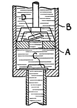
FIG. 40.—SECTIONAL VIEW OF A SUCTION PUMP
A suction pump should be called an atmospheric pump. The operation of such a pump is illustrated in Figure 40. A piston A slides in a cylinder B. There is an opening in the bottom of the cylinder which is normally closed by a clack valve C that opens upwardly. There is a similar valve D in the piston A. When the piston is pushed down it compresses the air in the cylinder, closing the valve C while valve D opens, permitting the air to escape. Then on the upward stroke the valve D closes and valve C opens permitting air to flow into the cylinder.[113] In this way the air in the pipe and cylinder are exhausted after a few strokes. As the air is rarefied and the pressure is reduced above the column of water in the pipe the greater pressure of the water outside the pipe forces the column to rise until it eventually flows through the valve in the piston and out of the spout of the pump. The maximum height to which water can be raised by a suction pump is thirty-four feet but in actual practice the lift seldom exceeds twenty-six to twenty-eight feet because the fit between the cylinder and piston is not perfect.
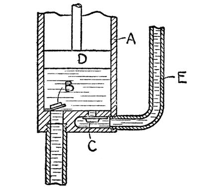
FIG. 41.—CONVENTIONALIZED SECTIONAL VIEW OF A FORCE PUMP
When water is raised to a greater height a force pump is used. Such a pump is shown in Figure 41. The pump cylinder A has two valves B and C. The valve B opens upwardly and valve C opens downwardly. The piston D is a solid member containing no valve. When the piston rises the valve C closes and valve B opens, letting water into the cylinder. On the reverse stroke the valve B closes and the[114] descending piston forces the water out through valve C into pipe E. The height to which the water may be lifted depends upon the power applied to the piston and not upon atmospheric pressure. In a fire pump two force pumps are used which alternately deliver water into an air chamber. The air is compressed by the water that enters the chamber and exerts a steady pressure on the water, forcing it out through the fire hose in a stream that is practically steady.
It is a decided disadvantage to install a force pump in a deep well because of the mechanical difficulty of operating the piston at a great depth. Often the suction and force pump principles are combined. The force pump piston and cylinder are located twenty-six and twenty-eight feet above the level of the water in the well with a pipe leading down into the water. The water is forced up into the cylinder by exhausting the air in the cylinder and pipe and then is forced out of the cylinder and up a pipe to the top of the well. This also has its disadvantages. In deep wells the pump piston must still be located and operated at considerable depth.
THE AIR LIFT
A much more simple pump for deep wells is the air lift in which there are no valves and no piston. The pump consists of two pipes that are let down into the water. (See Figure 42.) The larger pipe is open at the top and bottom, and the smaller pipe discharges air into the bottom of the larger one. This air being directed upward has a lifting effect, and mingling with the water in the pipe produces a sort of froth which is so much lighter than solid water that the atmospheric pressure on the water[115] in the well is sufficient to raise the froth. The water is thoroughly aerated and to a large extent purified by this system of pumping, so that the air lift commends itself particularly for city waterworks. Sometimes a series of air lifts are used which lift water by successive stages to a greater height than would be possible with a single direct lift.
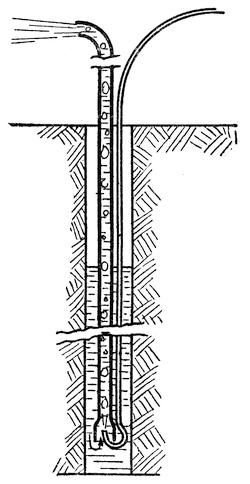
FIG. 42.—PUMPING WATER WITH COMPRESSED AIR
EXCAVATING THROUGH QUICKSAND
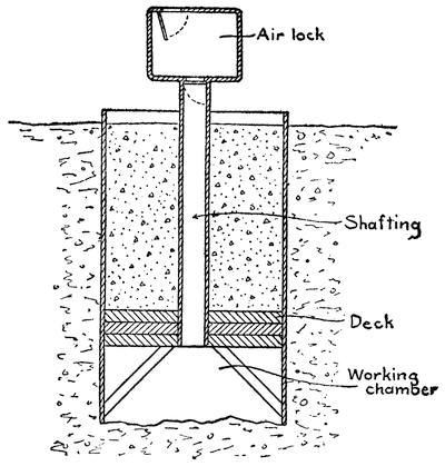
FIG. 43.—SECTIONAL VIEW OF A PNEUMATIC CAISSON
Centuries ago it was realized that it would be possible for men to descend into the open sea if they were protected by a bell-shaped chamber, for the air trapped in the chamber would furnish them with oxygen requisite for breathing purposes, and would prevent the water from drowning them out. This same idea of a diving bell is used on land when sinking a shaft through quicksand or water-bearing strata. A large box or caisson is used. (See Figure 43.) This box may be either cylindrical or rectangular, and it is open at the top and bottom. The lower edges of the box are shod with steel and form cutting edges that will sink into the soil that is being excavated. At a height of about seven feet above the bottom of the box there is a transverse diaphragm known as the deck, and the space below is known as the working chamber.[117] This deck is very strongly constructed, as it has to support the weight of the concrete shaft that is built above it. Laborers, commonly known as “sand hogs,” enter the working chamber and dig out a shallow pit in the floor of clay or sand. This pit is then extended to the cutting edges of the caisson. The caisson thus undermined settles down into the excavation and another pit is started. In this way, step by step, the caisson is sunk into the ground. In order to overcome the friction of the caisson against the sides of the excavation and to insure its sinking, it is heavily weighted. When water-bearing sand is reached, compressed air is admitted into the working chamber to force the water out. When the air pressure is greater than the water pressure it drives the water out of the sand in the working chamber, so that the men can work in perfectly dry ground, even though the surrounding sand may be so saturated with water as to form a quicksand.
Of course the farther the excavation proceeds below the water level the greater the air pressure required, and the caisson would be blown up out of the ground by this air pressure or would float on the water were it not for the weights with which it is loaded. When an open shaft is to be dug, pig iron is loaded on the caisson to force it down, but in most work the object is merely to sink a concrete column down to rock and so the caisson is filled with concrete above the deck. Sections are added to the caisson as it sinks into the ground, and these sections are filled with concrete. This method of building the column facilitates the work of laying the concrete, and at the same time provides the weight necessary to overcome the buoyancy of the caisson[118] and the skin friction on the side walls of the excavation.
After the caisson has been carried down to rock and a good seat has been blasted out of solid rock, the working chamber is completely filled with concrete and the concrete shaft is thus anchored to the rock.
THE AIR LOCK
Access to the working chamber is had through a central shafting. In order to hold the air pressure in the working chamber and yet provide for the entrance of men and materials, an air lock is fitted to the upper end of the shafting. This air lock, as shown in Figure 43, consists of a chamber formed with a trapdoor at the top and the bottom. Both doors open downwardly. To enter the caisson, the bottom door of the chamber must first be closed and means are provided for doing this from outside the air lock. The compressed air in the chamber is then let out through a valve, and when the pressure drops almost to normal the upper trapdoor falls open of its own weight, giving access to the chamber. After entering, the upper door is closed while compressed air is admitted into the chamber; the air pressure then serves to hold the upper trapdoor closed. The bottom door, in the meantime, has been kept closed by the air pressure below, which is greater than that above the door. But after sufficient air has been introduced into the chamber to equalize the pressure on both sides of the lower trapdoor, it falls open of its own weight. The occupants of the chamber can then proceed down a ladder to the working chamber. When leaving the caisson, the action of the air lock is reversed. The bottom door is pushed up and held closed for a moment[119] while air is released from the chamber, when the greater pressure beneath will hold the door closed, and after the pressure within the air lock has been lowered practically to normal, the upper door drops of its own weight, permitting the occupants of the chamber to climb out. The same process must be undergone by buckets loaded with sand or earth from the excavation and by empty buckets returning to the working chamber.
More time is required for a man to pass through an air lock than for a load of sand or any inanimate load. In some of the larger caissons a separate small air lock is provided just for the use of the workmen. In the air lock the pressure must be built up slowly so that it will permeate a man’s whole system. When we realize that the pressure that men have to support in caisson work may amount to from fifty to one hundred tons on the whole body, it is difficult at first to understand why the body is not flattened out like a pancake. It is only by permitting the system to absorb the pressure so that there is as much internal pressure as that outside that a man is able to enter a compressed air chamber without harmful results.
THE CAISSON DISEASE
Compression is rather annoying to a man who has not experienced the sensation, but the principal danger comes in decompression, particularly after a person has been in the working chamber for a long time. When breathing compressed air much larger volumes of oxygen are taken into the lungs at each breath than in the ordinary atmosphere, and one feels decidedly exhilarated by this unusual supply of stimulating oxygen. But with the oxygen large[120] volumes of nitrogen are taken into the system as well. The nitrogen permeates the blood while the oxygen is consumed and exhaled in the form of carbon dioxide. The longer a man is exposed to the pressure the more nitrogen does he absorb. When the pressure is released suddenly the nitrogen begins to froth, just as a bottle of soda water does when the stopper is removed. The nitrogen bubbles in the small veins stop the circulation and produce the dreaded “caisson disease” which makes itself felt in the form of severe cramps and excruciating pains. Not infrequently this disease ends in death. By reducing the pressure gradually the nitrogen is enabled to pass off completely without bubbling or frothing, just as it is possible to let out the gas from a soda bottle without frothing by permitting it to escape through a pin hole in the stopper. The surest cure for a victim of the caisson disease is to put him immediately into what is known as a “hospital tank” and build up the pressure in the tank equal to that which he has just been subjected to in the caisson, after which the air in the tank is let out so slowly that there is plenty of time for the nitrogen to pass off without forming bubbles.
A pressure of forty-five pounds per square inch above that of the atmosphere is considered a severe pressure for excavation work. But work has been carried on in pressures up to fifty-two pounds, corresponding to a depth of 120 feet below water level.
Now that the cause of the caisson disease is understood formulas have been worked out to insure proper decompression. On one occasion a diver descended 306 feet into the ocean where the water pressure was 133 pounds on[121] every square inch of his body. This meant that the air which was pumped down to him had to be compressed to the same pressure. The diver actually remained at the bottom only a very short time, but it took two hours and three-quarters to bring him to the surface. He came up half the distance very quickly and then had to rest on the bottom rung of a Jacob’s ladder. The rungs on this ladder were ten feet apart and he was instructed to rest on each rung a certain specified time. When he was ten feet below the surface he had to wait three-quarters of an hour for the last trace of nitrogen absorbed by his blood to pass off.
BORING TUNNELS THROUGH RIVER BEDS
It is comparatively simple to sink a vertical shaft into water-bearing soil, but a horizontal shaft involves serious difficulties. The action of a diving bell is easily illustrated by inverting a tumbler and pressing it down into a basin of water. The air trapped in the tumbler will keep the upper part of the glass dry, and by inserting a tube in the tumbler it is possible to fill the tumbler so full of compressed air as to drive out all the water. This is virtually what is done in the caisson; but when excavating a horizontal bore, the caisson must be turned on its side. Turn the tumbler on its side and it is impossible to keep the water out of it, no matter how much air we may blow into it. The reason for this is that the pressure on the open end of the tumbler is not uniform. At the bottom, where the water is deeper, it will be greater than at the top. If air is pumped in to equalize the water pressure at the upper edge of the glass, it will not prevent water from flowing in at the bottom; and if it be equal to that at[122] the bottom, the water pressure at the top cannot hold the air in and keep it from pouring out.
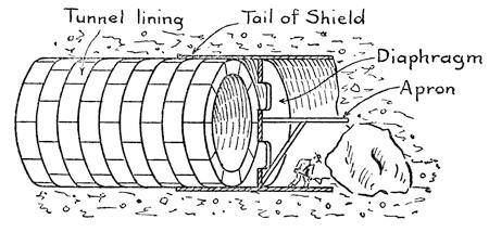
FIG. 44.—SECTIONAL VIEW OF A TUNNEL SHIELD
Fortunately most of the soil through which a subaqueous tunnel is driven is not very fluid. It is either sticky, as in clay, or sluggish enough to prevent the water from flowing in rapidly. If there is enough cover of silt or earth above the tunnel bore, it will help to hold the air in the tunnel. When the bore comes very close to the surface of the bed of the stream that is being tunneled, loads of clay are dumped along the line of the tunnel to provide the requisite cover. In tunnel boring a shield is used which is the equivalent of the caisson in vertical boring. The shield is a cylindrical box with a diaphragm across it corresponding to the deck of the caisson. (See Figure 44.) In front of the diaphragm there is a small working chamber which is protected above by an extension of the shield known as an apron. In the diaphragm there are a number of doors at different levels, which may be closed in case of danger. If work is proceeding near the top of the shield, the upper doors are opened and the pressure is regulated to equal the water pressure[123] at that level. If the work is carried on near the bottom of the shield, the upper doors are closed and only the lower doors are open, and the pressure is increased to equal the water pressure at that point. Sometimes the material is of such a nature that the men can safely pass out of the doors into the working chamber outside, but more often it is possible to work only within a limited area immediately in front of the doors.
When the material is very soft it is often unnecessary to do any actual excavation by hand in front of the diaphragm. The shield is merely pushed forward through the mud or silt and the doors are opened to let the material flow in through them. Workmen dig out this mud and it is hauled out of the tunnel. Whenever bowlders are encountered it is necessary for the men to work outside of the diaphragm to chip away the rocks with compressed-air drills, or else bore them and blast them with small charges of dynamite.
In quicksand the material is so fluid that it is unsafe to open the ordinary doors of the caisson, and they are then provided with shutters which are raised one at a time, to permit of operating on a very small section of the head of the tunnel. After enough material has been excavated from in front of the shield, the latter is pushed forward and the excavating is renewed.
Unlike caisson work, the weight of the shield is of no assistance in making it penetrate the soil, nor is it possible to move the entire lining of the tunnel with the shield. The tunnel is lined with rings of cast iron which are bolted together, the rings themselves being made up of heavily ribbed curved plates. The shield is formed with a “tail[124]” which fits over the end of the tunnel line like a cap. When the shield is to be pushed forward, a set of hydraulic jacks are fitted between the end of the tunnel lining and the diaphragm of the shield, and by means of these the shield is given a shove forward far enough for a new section of the cast-iron lining to be added within the tail. The tunnel-lining rings are usually sixteen inches wide so that it is customary to move the shield ahead sixteen inches at a time or just far enough for a new ring of lining to be installed. Of course, the tunnel is fitted with air locks by which men can enter the working section without permitting the compressed air therein to escape, and these locks are just like those used in sinking a caisson, except that they are horizontal instead of vertical.
QUELLING OCEAN BILLOWS WITH AIR
Air is also used in another and very novel way to battle against water. In this case it is not quiet water pressure, but the tremendous power of ocean storms that is combatted.
The influence of a shoal upon ocean waves has often been observed. A sand barrier even when submerged to a depth of twenty or thirty feet will break the waves of a heavy storm and leave an area of comparatively quiet water behind it. The reason for this is that the water in the waves does not travel with the waves, but undergoes local oscillatory motion. This motion is in the form of circular or elliptical currents which travel in a vertical plane. When a sand bar is encountered it interferes with these local currents and breaks up the waves.
Knowing this to be the case, it occurred to Mr. Philip Brasher that some other means of disturbing[125] the rhythmic movement of the water might be found, and he determined to try the experiment of using compressed air for this purpose. Accordingly he laid a perforated pipe under water and connected it with an air compressor. Then when a storm arose air was pumped into the pipe and it rose in bubbles through the water. The effect of this upward movement of air was instantly observable. It upset the rhythmic water currents and the waves which struck this wall of air bubbles curled and broke as if they had encountered a shoal of sand.
Several exposed piers on the Pacific coast have had a pneumatic breakwater built around them so as to protect them or ships lying alongside from being pounded by the waves. There is no expense attached to the breakwater except in time of storm when the air pumps must be kept going. One important advantage of the breakwater is that it does not block navigation. A ship can sail right over the wall of bubbles and find refuge behind it.
CHAPTER VIII
AIR SPRINGS AND CUSHIONS
UNLIKE water, air is a highly compressible, elastic fluid, and as such furnishes an excellent medium for the storage of energy. It acts just like a clock spring into which energy may be introduced and stored by winding or compressing the spring. The energy remains locked up in the spring and when the spring is released, it gives back just as much energy as was put into it, except for slight frictional and heat losses. Air is a much better spring than steel or any other metal because it never loses its elasticity from fatigue and because it has an enormous capacity for the storage of energy. It possesses one serious drawback, however. Much of the energy that is expended in compressing it is converted into heat. If the air were to be used immediately and without transmitting it to a distance, there would be no advantage in extracting the heat, but heat cannot be stored in air for long and it would gradually escape from the storage reservoir or air receiver and from the pipes leading the air to the machines that it was to operate. As the heat escaped it would lower the pressure of the air and hence much of the energy would be lost.
HEAT OF COMPRESSION
In Chapter V we described a hydraulic system of compressing air and noted that one of the advantages[127] of this system is that it delivers air cooled to the temperature of the water. This, of course, does not mean that there is no loss due to heat. The air bubbles as they are compressed are cooled by the water that compresses them; in other words, the heat of compression passes off into the water, making the water warmer than it would otherwise be. Heat is not produced without expenditure of energy and a certain proportion of the water power is thus wasted.
In most cases air is compressed by steam or electrically driven compressors, and in such machines the heat due to compression is a serious matter. The air cylinders are water-jacketed to carry off the heat. But air is a poor conductor; it acquires heat faster than it can give it off to the water surrounding the cylinders. In compound air compressors the air compressed in one cylinder is cooled before being passed on to the next cylinder, where it is further compressed. The heat loss in compressing air in a single stage up to 100 pounds gauge pressure is about 30 per cent. Air that enters a compressor at the normal pressure of the atmosphere and with an initial temperature of 60 degrees F., if not cooled will become heated to 415 pounds gauge pressure. The higher the initial heat of the air, the greater the rise of temperature. If a volume of air be subjected to 294 pounds gauge pressure, it will occupy about one-tenth of its former volume. If the air was introduced into the compressor at zero, it would acquire a temperature of about 650 degrees; if introduced at 60 degrees, it would show an increase of about 800 degrees; and, if started at 100 degrees, it would show an increase of 900 degrees in passing through the compressor. This shows the advantage[128] of compressing the air in stages and cooling the air between stages.
Sometimes the heat developed is sufficient to produce a disastrous explosion. Air is noncombustible, but the oils used to lubricate the compressor are vaporized by the heat and when mixed with air form a powerful explosive. Care has to be taken that none but high-grade oil with a high flash point be used in the compressor and that the temperature of compression does not rise to near the flash point lest the vaporized oil be ignited.
That fire can be produced by sudden compression of air has long been known in the Philippine Islands. The natives use a small air tube with a close-fitting plunger. Combustible matter is placed in the bottom of the tube, and on striking the plunger a sharp blow this is ignited.
When compressed air is used in an air motor it expands and in so doing absorbs heat. The more rapidly it expands, the more heat it absorbs. This heat it extracts from the motor and from the atmosphere into which it escapes, and it is a common occurrence to find a thick coating of frost around the exhaust port. This is due to condensation of moisture in the atmosphere or in the compressed air itself, which, because of the rapid extraction of heat, is converted into snow. On cold days enough frost may be produced in the exhaust pipe to clog it and interrupt the operation of the motor, and frost sometimes clogs the air lines leading to the motor.
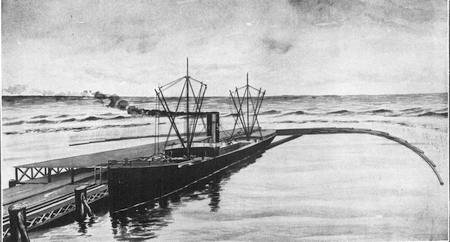
WHARF ON THE PACIFIC COAST PROTECTED BY A PNEUMATIC BREAKWATER
Air issuing from the submerged perforated pipes breaks up the waves
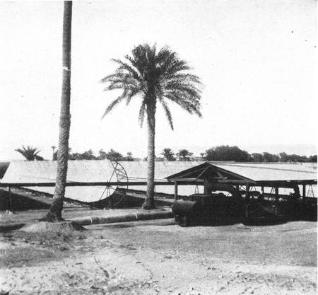
GENERAL VIEW OF A SUN POWER PLANT IN EGYPT
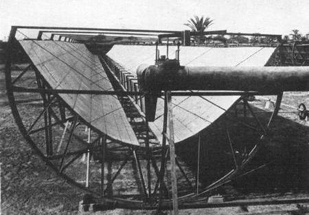
CLOSE-UP OF ONE OF THE REFLECTORS SHOWING THE BOILER
The fact that compressed air on expanding is cooled, makes it an ideal power for use in mining machinery. Steam is inconvenient because of the difficulty of transmitting it to the machines without loss of heat, because it would heat the machines so that they cannot be handled readily and because the exhaust steam would fill the mine with an impenetrable fog; electricity is dangerous in mines that are apt to contain explosive gases, because the wires are liable to be broken and cause sparks by short circuiting, and because sparks are likely to form between the brushes and commutators of the motors; but compressed air has none of these objections, and, furthermore, the discharge from the machines furnishes the operators with ample supplies of fresh cool air which drives out disagreeable and dangerous gases.
AIR-DRIVEN HAMMERS
The ordinary rock drill is really a pneumatic hammer. The tool, which is chisel-shaped, is used as a hammer to pound a hole in the rock. The tool is driven up and down or in and out by compressed air bearing alternately on opposite sides of a piston. The elasticity of the compressed air acts as a cushion to relieve the machine from shock. The drill is mounted upon a tripod in such a way that it may be operated in any direction.
The pneumatic riveter is another form of compressed-air hammer. The machine is held in the hands, and the tool, which is rapidly reciprocated by air pressure, pounds the red-hot shank of a rivet. While this is being done an assistant holds a hammer against the head of the rivet. However, there is a type of riveter which has a U-shaped frame. One arm of the frame carries the reciprocating tool while the other reaches around and bears against the head of the rivet.
All sorts of tools have been built in which a small air-driven motor furnishes the motive power. There are hand drills in which the tool is revolved by a set[130] of pistons, shears for shearing sheep which operate somewhat on the principle of hair clippers, and pneumatic chisels used for chipping stone. Pneumatic motors are widely used in operating cranes and air hoists. They consist of a simple cylinder and piston, and are used for short, direct lifts of all sorts.
STOPPING TRAINS WITH AIR
Air has played a most important part in transportation. When the air brake was first introduced its purpose was to prevent collisions and provide greater safety of operation. It was not generally realized that efficient air brakes are not only a safety precaution, but a means of increasing schedule speeds. The more quickly a train can stop, the better speed it may make, particularly on a schedule that calls for frequent stops.
In the first air brake invented by George Westinghouse, the locomotive was provided with a reservoir in which air was stored and compressed by means of a steam-operated air pump. The cars were each provided with a cylinder and piston connected to the air reservoir through a valve conveniently located in the engineer’s cab. The piston of the air cylinder was connected with the air brakes so that whenever the engineer wished to stop his train he merely turned on the compressed air and all the brakes in the train were operated. This was a great saving over the previous system of providing brakemen to operate hand brakes.
Unfortunately, the problem of stopping a train was not as simple as all this. On a long train the cylinders near the engine were the first to receive pressure sufficient to operate the brakes, and as a result, the forward part of the train was retarded[131] more than the rear part at the start of the brake operation, and the train came to a stop with a series of jolts. Another serious disadvantage was the fact that an enormous reservoir was required to furnish all the air necessary for a long train. But the most serious drawback was the fact that occasionally a train broke apart and then the engineer was powerless to control the brakes of the detached portion of the train. If the accident occurred on a down grade, there would result a collision between the cars running by their own momentum and gravity and those attached to the engine. This led to the present system of reversing the process which consists in keeping air pressure constantly in the train pipe and setting the brakes by relieving the pressure in the train pipe.
Each car is provided with its own cylinder which furnishes the necessary air for the operation of its brakes. There is, of course, a main cylinder on the locomotive in which air is pumped at high pressure by a steam-operated pump. When the pressure of the main reservoir falls below a predetermined amount, the air pump starts operating automatically and continues until the requisite pressure is restored. Air from the reservoir is fed to the train pipe at a certain pressure and feeds the local reservoirs on the cars of the train. At each car it passes through a very ingenious triple valve, which consists of a cylinder with a double piston, one operated by pressure in the train pipe, and the other by pressure in the local cylinder. The piston operated by the pressure of the train pipe is larger than the other and consequently the valve piston is normally pressed back, uncovering a small port through which air from the train pipe feeds into the local reservoir. In[132] this way the air in each local reservoir is maintained at the same pressure as that of the train pipe. Whenever air is let out of the train pipe, the piston is pushed out by the excess pressure on the local reservoir side and uncovers another port which permits air to flow from the local reservoir to the brake cylinder operating the brakes. The advantage of this system is that each car is always supplied with sufficient power to act on the brakes immediately without having to draw its supply of air from the main reservoir. In case the train breaks apart, the air in the train pipe escapes and the brakes are set automatically.
There have been a number of improvements in air brakes aimed to make the operation of the brakes more uniform and to insure immediate action, even on a very long train. Modern express trains weighing 920 tons and traveling at a velocity of 60 miles per hour, can be brought to a standstill in 860 feet, or practically their own length. Automatic arrangements are provided to insure the application of the brakes at graduated rate, except, of course, when the emergency brakes are applied. As the speed of the train slows down the pressure is gradually relieved, otherwise the train would stop with a severe jolt. The rate of applying the brakes so as to provide a smooth retardation depends in large measure upon the weight of the train.
On the New York subways, it is interesting to note, every passenger who boards a train has his weight recorded by the brake mechanism, and allowance is automatically made for the inertia that his mass adds to the train when it is in motion. The weight operates through a system of levers to control the amount of pressure that is applied to the[133] brakes so that when the engineer operates the brake lever, he does not have to consider whether the cars are light or jammed full of passengers; the brake mechanism itself takes care of this.
PROPELLING CARS WITH AIR
If air can be used to stop a train, why cannot air be used to propel it? This question occurred to many inventors and they answered it by building air-propelled cars and locomotives. Pneumatic cars were tried out on street railways, but they have had to give way to electric cars which do not need to carry their power around with them, but can draw it from a central power plant through a trolley wire. In only a few situations, such as in mines where electric sparking is feared, are air-propelled cars and locomotives still used to any considerable extent.
However, air plays another and highly important part in transportation and here it is employed not to deliver energy stored in it, but to serve as a cushion. Without the soft, flexible grip of the air-filled rubber tubes with which automobile wheels are shod, high-speed motoring would be practically impossible. There is nothing that can compare with air for absorbing shocks and unevennesses in the road. Whenever an obstruction is encountered, not only is the shock absorbed by elasticity of the air, but the impact is immediately distributed uniformly over the whole tire, so that the strain on the tire is not localized and the life of the tire is correspondingly increased. There have been many attempts to introduce substitutes for pneumatic tires, such as combinations of metallic springs and straps, but these have failed, chiefly for the reason that they cannot distribute the shock as the pneumatic tire[134] does. Consequently they are not only liable to damage, but they do not absorb the obstructions as readily as the pneumatic tire does and the vehicle which they carry is subjected to heavy stresses and strains.
Air as a cushion is used to prevent the rebound of the springs of an automobile and is also widely employed in machinery to absorb the momentum of moving parts or to slow the action of a spring. In a door check, for instance, a powerful spring is provided which would slam the door shut were it not for the cushioning action of air. A plunger is connected to the door and slides in a cylinder on the door frame. The air compressed by the plunger can escape only very slowly through a small port.
AIR CUSHIONS FOR ELEVATORS
Air cushions are used in elevators to prevent too rapid a fall of the car in case of accident. The lower part of the elevator shaft is completely inclosed and fitted with steel doors to form an air pocket. The car fits the shaft closely enough to compress the air under it when it is moving downward. At normal speeds, this air escapes quite readily around the sides of the car and through cracks in the doors, but when the speed is excessive the air cannot escape fast enough and sufficient pressure is built up to retard the car so that it will strike the bottom with a moderate impact not at all dangerous to the passengers.
In the Woolworth Building, New York, the highest elevator shafts are 680 feet high and the air pockets are 137 feet deep—i. e., they reach up to the tenth story. If the car broke away from its supports at the top of the shaft it would be traveling at the rate of 132 miles an hour when it struck the air pocket,[135] but before it reached the bottom the air would bring it practically to a stop. Imagine a heavy automobile traveling at 132 miles per hour and brought down to a standstill in half a city block! The passengers would be hurled out of their seats, but in an elevator the passengers are standing and can brace themselves against the pressure produced by their own momentum. The velocity acquired in falling 543 feet to the air pocket must be overcome in 137 feet or ¼ of the distance. This means that the weight of each passenger is multiplied by four. A man who weighed 150 pounds would find that his pressure on the floor of the car had mounted to 600 pounds. One of the inventors of the pneumatic cushion for elevators was killed when testing out a car, not because of the impact of the car, but because he was foolish enough to sit in a chair. The chair gave way under his suddenly acquired weight and the poor man was fatally stabbed by one of the splinters.
Air jets are used for a variety of purposes ranging from tamping railway tracks to painting buildings. When a track is depressed under the tamping action of trains passing over it the ties must be raised and new ballast introduced under them so as to bring them up to level. In order to save hand labor and insure the perfect filling of all cavities a pneumatic tamper is sometimes used. The ballast, consisting of sand or gravel up to ¾ inch in diameter, is fed out of a hopper and meets a blast of air that hurls it into place like shot from an air rifle. This furnishes a very solid and compact road bed.
It is in much the same way that weather-stained stone walls are cleansed by means of a sand blast. The sand particles projected by the jet of air act[136] like myriads of tiny bullets which chip away the face of the stone.
LAYING CEMENT WITH AN AIRGUN
It is after this same fashion that the cement gun is used to project cement against wire reenforcement to form walls of buildings. Carl E. Akeley was led to the invention of the cement gun by his efforts to find an expeditious and economical method of mounting specimens of large animals for the Field Museum in Chicago. He constructed a pneumatic device for spraying cement and water upon a canvas-covered framework, thus building up a body upon which the skin of the animal could be mounted. This machine was improved and tried out successfully, on a large scale, in constructing buildings.
The machine as now constructed consists of a hopper into which a proper mix of sand and cement is introduced. Compressed air blows this mixture out of a nozzle. Here it meets a jet of water also propelled by compressed air. The water, sand, and cement combine and strike the wall or surface to be coated with such an impact as to make a compact fine-grained coating known to the trade as “gunite.”
Large surfaces can be painted much more readily and more evenly with compressed air than with a brush. A widely spreading air jet is used which draws the paint out of a receptacle, breaking it up into minute droplets that are projected as a mist against the surface, covering it with a uniform coating.
AIR AS A TENSION SPRING
So far we have been considering air as a compression spring. It may also be employed in a manner somewhat analogous to a tension spring. When[137] air is exhausted from a receptacle we have a partial vacuum which will produce work, but in the opposite direction from that produced by compressed air. Of course there is no such thing as suction, and it is the pressure of the atmosphere which is employed to do the work.
We are apt to overlook the fact that a vacuum cleaner depends upon atmospheric pressure to drag the dust and dirt out of a carpet. A vacuum cleaner would not work on the moon, where there is no atmospheric pressure. The apparatus consists of an air pump, usually driven by an electric motor, which exhausts, or partially exhausts, the air from a foot piece that is dragged along the carpet. As the air under atmospheric pressure rushes in through the carpet to take the place of the air that has been pumped out, it carries with it all loose particles of dirt. The dirt is filtered out of the air or a mechanical trap is provided to catch and retain the dirt while the air is allowed to escape. Large-scale vacuum cleaners are used for cleaning city streets. The dirt is loosened by revolving brushes and is then drawn up by atmospheric pressure into a tank.
Another use of atmospheric pressure is to be found in the pneumatic tubes which convey mail from one post office to another. Air is exhausted from the tube and when a carrier is inserted which fits the tube closely the atmospheric pressure behind it forces the carrier along to its destination. The same system is used to carry money to and from the cashier’s office in department stores.
In later developments of the pneumatic mail carrier compressed air was used back of the carrier, but the principle of operation was not altered. In[138] either case propulsion is effected by the difference of air pressure on the opposite sides of the car.
In 1869 Alfred E. Beach built an experimental subway line under Broadway, New York, near Warren Street. The line was only 200 feet long. A cylindrical car large enough to hold eighteen people, fitted the bore snugly and was propelled in one direction by compressing the air in the tunnel and in the other direction by exhausting the air.
CHAPTER IX
POWER FROM HEAT
THE TERM “water power” is a misnomer. There is no power inherent in water. It is gravity that makes water fall in cataracts or flow down a river bed, and hence it is the force of gravity that is responsible for the turning of our turbines and Pelton wheels. Water is merely the medium through which the force of gravity acts.
In the steam engine, water, again, serves as a medium and it is the energy of heat that is actually the working force. A closed vessel is partly filled with water and heat is applied to it. The water grows hotter and hotter until at a temperature of 212 degrees it begins to vaporize. The temperature of the water remains stationary until the space above the water is completely filled with steam at a pressure equal to that of normal air pressure. The steam gauge then registers zero. Continued application of heat raises the pressure of the steam and also raises the temperature of the water. When the steam gauge shows a pressure of 25 pounds per square inch, the water temperature is nearly 267 degrees; at 100 pounds it is over 337 degrees; at 200 pounds it is 387 degrees; at 500 pounds it is about 467 degrees. As steam is drawn off from the boiler a proportionate amount of water turns immediately into steam to take its place. If the boiler should burst, the entire mass of water would instantly flash into steam because its temperature is far above the boiling point[140] at normal air pressure. That is why the explosion of a steam boiler is so violent. If the boiler were entirely filled with steam the effect of an explosion would not begin to be so destructive as if the boiler were half full of water. It is really the explosion of water that does such serious damage.
When the steam pressure in a boiler corresponds to the temperature of the water it is said to be saturated. The water in a boiler boils violently when the steam is drawn off rapidly and tiny droplets of water are carried off in the steam, producing what is known as wet steam. Steam that carries no water particles in suspension is called dry steam. When the steam is heated above the temperature of the water by means of an auxiliary heating device or by some peculiar construction of the boiler, it is called superheated steam.
In order to economize fuel it is highly important that as much water surface be exposed to the heat as possible. This may be done either by passing the heat in tubes through the water or by passing the water in tubes through the fire. Locomotive boilers are of the fire-tube type. The flaming gases of the furnace pass through the boiler through a series of tubes that lead to the stack. In the water-tube boilers it is highly important that a good and rapid circulation of water be maintained, otherwise there might be local generation of steam with serious consequences.
THE GIFFARD INJECTOR
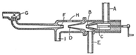
FIG. 45.—INJECTOR FOR INTRODUCING WATER INTO A STEAM BOILER
As steam is used from a boiler the water is slowly exhausted and it must be replenished with a fresh supply. In early days of the steam engine, water was pumped in against the boiler pressure by the use of powerful pumps, but in 1858 a man named Giffard invented a most ingenious apparatus by which steam of the boiler was used to force water in directly against its own pressure. This seems like lifting oneself by one’s boot straps. When the injector was first invented it seemed so impossible for it to work that engineers would not accept it until it had repeatedly demonstrated its operativeness. Even after it was accepted and in common use its mysterious operation was a subject of discussion for years. A sectional view of a Giffard injector is shown in Figure 45. Steam from the boiler comes down the tube A and passes out in a jet from the nozzle B. A needle valve C may be moved into the nozzle to reduce or shut off the jet of steam. The jet enters a conical chamber D which has a tube E that runs down into the water reservoir. The steam jet blows the air out of chamber D, producing a partial vacuum which draws water up the tube E and into the chamber D. When the water reaches the steam jet it is driven out of the chamber across a short open space into a slightly diverging tube or receiving cone F and through a check valve G into the boiler. At H there is a glass window through[142] which the action of the water jet as it rushes into the receiving tube may be watched. I is an overflow pipe leading back to the reservoir. When the steam flows into the cone B it gathers momentum and issues from the nozzle in a jet of high velocity. On striking the water it combines with the water and condenses, but at the same time it imparts its momentum to the water so that the water is given more than enough momentum to drive it into the boiler against the pressure in the boiler.
The pressure of steam is utilized to drive the piston of an engine or the steam may be set in motion by letting it issue from a nozzle, when its momentum may be employed to drive a steam turbine in the same way that a water jet drives a Pelton wheel but in either case it is heat that does the work. The steam expands as it moves the piston and as it passes through the nozzle its expansion is accompanied by a corresponding loss of heat.
As we have already noted, it was for the purpose of raising water that inanimate powers were first set to work. It was with the same object in view that steam was first employed.
HERO’S STEAM ENGINE
To be sure the first steam engine was invented by Hero, the disciple of Ctesibius, in the second century before Christ, and it was not a water-raising machine. It consisted of a hollow sphere (see Figure 46), mounted to rotate and fed with steam that entered it through the journals. The steam issued from opposite sides of the sphere through two bent tubes. The steam in issuing from the tubes reacted against the tubes, pushing them back and causing the sphere to revolve.
Every action is accompanied by an equal and opposite reaction. A bullet fired from a gun kicks the gun back. In order to push the bullet out of the barrel, the powder must have something to push against and the push against the gun is equal to the push against the bullet. Even if there were no bullet to be pushed the discharge of the powder would react against the gun. In order to push its own gases out of the gun, the powder must push back against the gun.
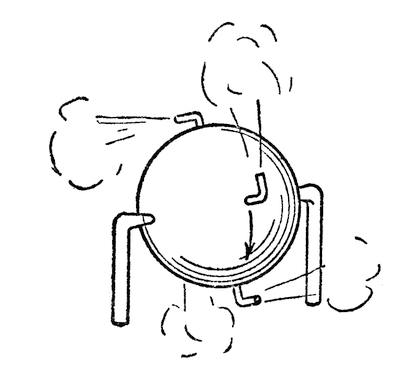
FIG. 46.—HERO’S STEAM ENGINE
In Hero’s engine, the steam, in order to push itself out of the sphere, must push against the bent tubes. We have a similar reaction motor in the revolving lawn sprinkler. The water issuing from the bent arms of the sprinkler forces them back and causes them to revolve. Were the arms radial and not bent the reaction would be there just the same, but it would be exerted against the center of the wheel and hence there would be no rotation.
Reaction has nothing to do with the pressure of the atmosphere as so many people imagine. A gun would kick just as hard and the lawn sprinkler or Hero’s engine would operate just as well and as fast[144] in a perfect vacuum. It was to demonstrate the principle of reaction that Hero built his steam engine. As far as we know it was never put to useful work and remained merely a scientific toy.
NEWCOMEN’S ATMOSPHERIC ENGINE
The first practical use of steam power was applied to the pumping of water from the deep mines of Cornwall. Newcomen’s engine, which antedated Watt’s by several decades, was known as an atmospheric engine. It consisted of a cylinder fitted with a piston, but the top of the cylinder was open. The piston was connected to one end of a lever or walking beam, the other end of which was connected by a chain with the plunger of a pump situated at the bottom of the mine shaft. Little power was required to lift the piston because it was counterbalanced by the chain and plunger attached to the opposite end of the walking beam. The real work was done in pushing the piston down and thereby raising the pump plunger. Steam under low pressure was let into the cylinder under the piston to raise it and then a jet of water was sprayed into the steam-filled cylinder. This condensed the steam, producing vacuum and the atmospheric pressure acting on the upper surface of the piston forced the piston down, raising the pump plunger. The engine ran very slowly, making only about 15 strokes per minute. Later it was improved, producing about 30 strokes per minute.
WATT’S STEAM ENGINE
Watt was the first man to build an engine in which the real work was done by the pressure of steam as in modern steam engines. As long as the steam engine[145] was used for pumping water the reciprocating piston could be connected directly to the pump plunger and it was unnecessary to exert power on both sides of the piston, but in 1782 Watt obtained a patent on a double-acting engine. Steam was admitted first on one side of the piston and then on the other. The walking beam was connected by means of a connecting rod to a crank on a shaft that carried a flywheel, and the seesaw motion of the beam was converted into rotary motion of the wheel. This opened up new industrial opportunities for the steam engine.
The steam was exhausted from the cylinder into a condenser, i.e., a chamber, in which a spray of water converted the steam into water, producing a vacuum, thereby relieving the piston of back pressure and virtually adding that much more power to the steam operating on the opposite side of the piston. A pump driven by the engine drew the water and the air liberated from the condensed steam out of the condenser.
Watt invented an ingenious governor to control the flow of steam to the engine and insure a uniform motion. (See Figure 47.) This governor consisted of a pair of levers hinged to a revolving shaft and each provided with a ball weight at its free end. The shaft was revolved by the engine and if the engine tended to run too fast the balls were thrown out by centrifugal action. In so doing they operated a throttle valve cutting down the steam supply. When the engine slowed down the balls would drop, admitting more steam. In this way the speed of the engine was kept within close limits. The ball governor in improved form is still widely used in stationary engines.
USING THE HEAT IN THE STEAM
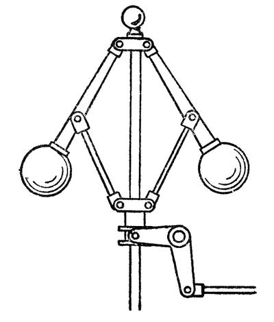
FIG. 47.—WATT’S BALL GOVERNOR
Another of Watt’s inventions which has proved of highest importance in steam engineering was the cut off. In his first engine the piston was subjected to the full boiler pressure throughout its stroke, and the steam that poured out of the exhaust port of the cylinder at the end of the piston stroke was almost as hot as that which entered the cylinder at the beginning of the stroke. The heat that goes out in the exhaust represents just so much wasted energy. Watt realized this and so he invented a valve which would cut off the flow from the boiler before the piston had completed its stroke. Then the steam back of the piston would continue to expand because of the heat within it and would keep on pushing the piston. Of course, the pressure would gradually diminish and there would be less power in the stroke than if the full boiler pressure were pushing the piston all the way, but this loss of power is[147] offset by the saving in steam and in the fuel used to heat the steam. The point at which the cut-off takes place depends largely upon the pressure of the steam. If the steam is cut off when the piston has made only one-fifth of its stroke, one-fifth as much steam will be used at each stroke as would be the case if the steam were used nonexpansively. However, in actual practice the expansion of the cut-off steam instead of being five times would be only about four times, because of the clearance that must be allowed between the piston and the end of the cylinder. If steam of 100 pounds absolute pressure is used, the average pressure throughout the piston will be only about 57 per cent of the full pressure of the steam in the boiler, but each pound of steam will actually do .57 × 4 = 2.28 times as much work as it would if used nonexpansively. All sorts of valve gear have been invented to admit steam quickly and cut it off at the proper point to produce the most efficient result.
In low-pressure cylinders in order to prevent loss of heat through the wall of the cylinder, the latter is steam-jacketed. In other words, there is an outer casing surrounding the cylinder and between this casing and the cylinder steam is admitted to keep the cylinder walls hot.
In order to make full use of the heat in steam it is, in some engines, sent through a series of two, three, and even four cylinders. The exhaust from one cylinder goes into a second larger cylinder. From here after doing work on a piston it discharges into a third still larger cylinder and from that may be led into a fourth cylinder. The cylinders must be progressively larger to allow for the expansion of the steam.
The ordinary steam engine labors under the disadvantage of having to start and stop its pistons at the end of each stroke. Every body possesses inertia, whether it be moving or at rest. If it be at rest, it takes much more energy to set it in motion than to keep it moving. In fact it would keep on moving without further expenditure of energy were there no friction and no forces acting against it. In order to stop the body energy must be expended to overcome its inertia. The more rapidly a body is started and the more quickly it is stopped, the more work must be done in overcoming its inertia. In a steam engine not only the piston but other parts connected to it may be required to reciprocate several hundred times per minute. A great deal of energy is uselessly expended in starting and stopping these parts.
Many efforts have been made to produce a rotary engine in which the piston rotates instead of reciprocating, thus doing away with the work of overcoming inertia. However, there are serious obstacles to the construction of such an engine, and as yet no truly efficient and practical rotary engine has been built.
DE LAVAL’S STEAM TURBINE
However, there is another type of engine in which the steam is applied continuously and all the parts revolve. Such an engine was the reaction turbine invented by Hero, to which reference has already been made. Modern turbines, however, are of very different construction. They resemble the Pelton wheels and turbines used in developing water power, differing from them mainly in the fact that use is made of the expansive energy of steam which is lacking in water. In the De Laval steam turbine a[149] wheel is used which has a series of curved buckets all around its periphery that are closed at the outer end by a circular rim. (See Figure 48.) Steam is directed against this bucket, not tangentially as in a Pelton wheel, but from the side. Several steam nozzles are employed and as the steam jets strike the buckets and sweep around their curved surfaces they react against the buckets and drive the wheel around. In order to operate efficiently the velocity of the steam must be very high and the wheel must also turn at high speed. When steam flows through a diverging nozzle its velocity is greatly accelerated by its expansive effort. Such nozzles are used in the De Laval turbines and the steam issues from them with a velocity which may be higher than that of a rifle bullet. The buckets are forged and the hard-scale surface is left on them; otherwise they would wear away quickly under the action of the powerful jets of steam.
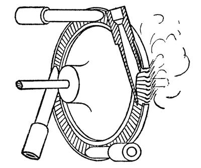
FIG. 48.—THE DE LAVAL STEAM TURBINE
The turbine wheel may revolve at a speed of 30,000 revolutions per minute. Such a tremendous[150] speed has its disadvantages. If a wheel is to run smoothly it must revolve on its center of gravity. A lopsided wheel, or one that is mounted a little off center, produces a pounding action which imposes a serious strain upon the bearings and the revolving parts. The wheel tries to turn on its own center of gravity and will do so if permitted to. It is impossible to balance a wheel so perfectly that the axis it turns on passes exactly through its center of gravity. At ordinary speeds this slight eccentricity is so slight that it is practically negligible, but when we have to deal with 30,000 revolutions per minute the least divergence between the center of rotation and the center of gravity will produce dangerous strains. For this reason the wheel of the De Laval turbine is mounted on a flexible shaft and on floating bearings, so that it will automatically find and turn on its own center of gravity. In order to utilize the power developed in the wheel, gearing must be used to step down the speed.
PARSONS EXPANSION TURBINE
The Parsons steam turbine resembles a water turbine in its action. Instead of having a few nozzles directing steam against the buckets there is a nozzle for each bucket, and instead of a single wheel there is a series of them through which the steam passes, successively passing through a set of nozzles between each wheel. The nozzles are formed of blades on the periphery of stationary wheels. These blades are curved in the opposite direction to the blades on the revolving wheels, as shown in Figure 49. Steam in passing through the ring of curved stationary blades is divided up into a series of jets which strike the curved blades of the first wheel. In passing[151] through this wheel the direction of the stream is reversed, and it enters between the second set of stationary blades, which turn it back again and direct it against the next wheel. Thus the steam pursues a sinuous course through the series of wheels. To allow for the expansion of the steam the blades are made progressively longer and the wheels of progressively larger diameter from the inlet to the exhaust end of the engine.
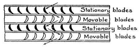
FIG. 49.—PERIPHERAL VIEW OF THE BLADES OF A PARSONS TURBINE
The Curtis turbine combines the De Laval and the Parsons principles. The steam enters through a series of nozzles which are of the expanding type, then it goes through a series of moving and stationary blades, as in the Parsons turbine, from which it enters another set of expanding nozzles and gains velocity and momentum before passing through the second series or stage of moving and fixed blades. (See Figure 50.)
Steam turbines are particularly adapted for use in electric power plants. The speed of rotation of the Parsons and Curtis types is much lower than that of the De Laval and hence the electric generators may be directly driven by them without the interposition of any gearing. They can be built of larger power than the reciprocating engines because they are so economical of space.
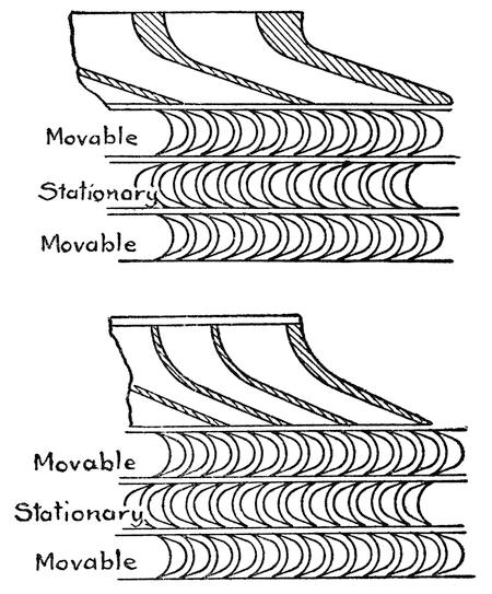
FIG. 50.—PERIPHERAL VIEW OF THE BLADES AND NOZZLES OF A CURTIS TURBINE
A good comparison of turbine versus reciprocating engines is offered by the 74th Street power station of the Manhattan Elevated Railway, New York. This station, which was completed in 1901, was equipped with eight huge reciprocating engines, each developing 8,000 horsepower normally, and capable of delivering a maximum of 12,500 horsepower. The whole plant, therefore, had a maximum capacity of 100,000 horsepower. Gradually these[153] units have been giving way to steam turbines of much higher power, and in 1919 there was installed one powerful turbine which alone was capable of developing as much power as the entire plant of 1901. This is a triple-compound turbine comprising one high-pressure turbine and a low-pressure turbine at each side. Steam enters the high-pressure turbine at 205 pounds pressure to the square inch and then exhausts into the low-pressure turbines, passing from them into condensers which operate under 29 inches vacuum. Each turbine drives a separate generator and the combined horsepower of the whole unit is about 100,000, while the floor space occupied is only 50 by 52 feet.
The economy of space and of fuel offered by the steam turbine is of great value in the power plants of ships, and this form of prime mover has been installed on modern high-speed passenger liners and also on high-speed war vessels. While in certain respects the turbine is ideal for such service, there are two handicaps which must be overcome. In the first place, the most efficient speed for the turbine is considerably higher than the efficient speed of the propeller and some means must be provided for stepping down the speed. In the second place, the turbine cannot be as economically controlled as a reciprocating engine and its direction of rotation cannot be reversed, so that difficulties are encountered in maneuvering the ship in harbors. It is no simple matter to gear down the high speed and enormous power of a turbine, However, an elaborate system of gearing has been provided for this purpose which has proved satisfactory even in powerful battle cruisers. The British battle cruisers with a power plant of 134,000 horsepower are driven by[154] geared turbines. To reverse the propellers separate low-power turbines are used.
A more attractive system of control is to have the turbines drive electric generators and then use the electric power to drive the propellers through motors mounted on the propeller shafts. The electric power can easily be controlled from the bridge and the propellers may be reversed by reversing the motors. However, the disadvantage of the electric system is that it occupies a great deal of space, particularly in plants running over 100,000 horsepower.
CHAPTER X
BURNING FUEL IN THE ENGINE CYLINDER
ONE OF the handicaps of steam power is that the heat produced by the combustion of fuel is not used directly to drive the piston. A large part of the heat energy in coal goes up the chimney or is wasted by radiation from the furnace walls. With anthracite coal in the furnace the loss may be as low as 22 per cent in the very best types of boilers. In the engine other serious losses occur, so that in the best condensing reciprocating steam engines the power delivered is only 10 to 16 per cent of that stored in the fuel. In locomotives the efficiency is as low as 4 to 6 per cent. In turbines the steam is used to better advantage and the actual power delivered may run up to 20 per cent of that in the fuel.
In internal-combustion engines the furnace and boiler losses are largely overcome by burning the fuel right in the cylinder, where the heat energy of the combustion may be utilized directly upon the piston. There are other losses, however, so that the most efficient gasoline engines deliver only 28 per cent of the energy in the fuel, and coal-gas engines may run up to 31 per cent.
A wide range of fuels may be used in an internal-combustion engine. They may be either gaseous, liquid, or even solid. In stationary engines hydrogen, coal gas, natural gas, blast-furnace gas, and[156] producer gas are employed to advantage. Volatile fuels, such as alcohol, bensol, gasoline, and kerosene, are turned into a mist or vapor and then burned as a gas. In engines of the Diesel type any liquid fuel ranging down to thick crude oils may be employed, and in one type of engine, which, however, has not proved commercially practicable, coal dust is burned in the cylinder.
BURNING AIR IN THE AUTOMOBILE ENGINE
Owing to the widespread use of automobiles, the general public is better acquainted with internal-combustion engines than with steam engines. Nevertheless, there are many elementary facts in connection with gasoline engines that are not generally known. The average motorist probably does not realize that he burns far more air in his motor than gasoline, and he probably does not understand why it is that the mixture of gasoline vapor and air must be compressed before it is ignited, or why only one out of four strokes of the piston is a power stroke.
If a volume of gasoline vapor be thoroughly mixed with an equal volume of air, the mixture will not explode. Only when there is an excess of air will combustion take place, and the most intensive explosion takes place when there are nine parts of air to one part of gasoline vapor. Where gasoline is vaporized in a carburetor the best mixture is one part of gasoline-saturated air to eight parts of pure air. Hence it is mainly air that is burned in an automobile engine.
The energy of combustion is much greater when the mixture is compressed. The particles of gasoline and air are forced into more intimate contact by the compression. The same thing is true of gunpowder.[157] If gunpowder is ignited in the open air, it will burn quickly, but not with explosive violence. If, on the other hand, the powder is compressed in a cartridge and is then ignited, an explosion takes place. Nearly twice as much gas was required in the early noncompression-type motors as is required to-day in the compression motors of the same power.
In an internal-combustion engine the cylinder serves as a furnace. This “furnace” must be charged with fuel, and after the fuel has been burned the “ashes”—i. e., the products of combustion—must be removed. The piston serves as the furnace stoker.
In the ordinary four-cycle engine the action of the piston is as follows: On the first or down stroke of the piston a mixture of air and gasoline vapor is drawn into the cylinder; on the next or rising stroke the charge is compressed. Then the charge is ignited by an electric spark, and the rapid combustion of the charge produces gases which drive the piston down. On the fourth stroke the piston rises again and pushes the burnt gases out of the cylinder. The piston receives energy intermittently, or only once out of four strokes, and a flywheel has to keep it going the rest of the time. It is just like propelling a bicycle with a single pedal and pushing the pedal every other time it comes out. It can be done as long as the wheel is moving fast enough to carry itself along between power strokes. Naturally a single-cylinder motor cannot be slowed down very much without stalling, and it will not start of itself because it needs outside help in stoking its furnace before it acquires the power to do this job alone.
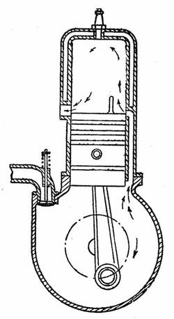
FIG. 51—SECTIONAL VIEW OF A TWO-CYCLE ENGINE
There is a two-cycle type of motor in which the burnt gases are removed from the cylinder, not by the piston, but by the injection of the unburnt fuel mixture. On the upward or compression stroke the piston not only compresses the mixture in the cylinder, but draws in a fresh charge of fuel into the crank case, and when the piston is driven down by the combustion of the fuel in the cylinder, the charge in the crank case is compressed until, near the end of its stroke, the piston uncovers a port in the cylinder through which the fuel from the crank case is forced in. (See Figure 51.) Just before this occurs the piston uncovers an exhaust port in the opposite side of the cylinder, and the burnt gases start to[159] flow out before the fresh charge of fuel pours into the cylinder. The incoming gas is directed upward so as to completely scavenge the cylinder of all burnt gases.
There are no bothersome poppet valves in this engine. The piston itself acts as a valve, opening and closing the inlet and exhaust ports as it slides by them. Every other stroke of the piston is a power stroke, so that the engine acts like a one-pedal bicycle, which receives a push every time the pedal comes around. Unfortunately, the burnt gases are never completely scavenged, and the fresh charge of fuel is always more or less diluted by the product of combustion remaining from the previous charge. This represents just so much loss of power, and may interfere with the ignition of the charge. For this reason the four-cycle engine is generally considered more reliable and efficient, and is far more generally used, particularly on motor vehicles.
To overcome the intermittent character of the internal combustion engine a number of cylinders are used, which come into play successively. In the four-cylinder motor one piston is always on the power stroke. In recent years the number of cylinders has progressively increased from four to six, eight, and twelve cylinders, while in racing power boats the number of cylinders has gone up as high as twenty-four.
COOLING THE CYLINDERS
The temperature of the combustion in a gasoline engine may be over 3,000 degrees Fahrenheit. Evidently it would melt the cylinder walls were not special provisions taken to keep them cool. The usual method is to surround the cylinders with[160] water which absorbs the heat, and then cool the water by passing it through a radiator. Air driven by a fan through the radiator carries off the heat. Of course this represents just so much wasted energy and lowers the efficiency of the motor, but it is the most convenient way of getting rid of the intense heat of combustion. Smaller motors, such as are used on motorcycles, have their cylinders cooled by direct action of air on the outer surface of the cylinder. The heat radiated depends upon the surface exposed and the velocity of the air current. The radiating surface of the cylinders is increased by forming them with external ribs or flanges, so that the air that flows over them, while the machine is in motion, carries off enough heat to keep the temperature of the cylinders within safe limits. In some systems, particularly in the case of stationary engines, to insure a good circulation, the air is positively driven against the flanges by means of a fan.
There are serious disadvantages in using water to cool an engine. Besides the bother of keeping the water system supplied with water there is the danger of clogging the radiator with lime deposits, and in extremely cold weather the water is liable to freeze and burst the water jackets or the radiator; for this reason, air cooling is recommended by some for automobile engines. In certain air-cooled automobile engines the cylinders are air-jacketed; that is, they are surrounded with casings through which the air is sucked by a powerful fan driven by the engine shaft, so that the air is bound to flow if the engine is turning. The cylinders are ribbed, so that they present a large radiating surface.
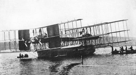
Copyright, Kadel & Herbert
GIANT CAPRONI HYDROAEROPLANE WHICH WAS WRECKED AT LAGO MAGGIORE
Seating capacity 100 persons; power, eight 450-h.p. Liberty motors

A BOAT OF STONE—THE CONCRETE STEAMSHIP “FAITH”

THE “VIRGINIAN,” THE LARGEST LOCOMOTIVE IN THE WORLD
Length over all, 97 ft.; weight of engine, 684,000 lbs.; of tender, 214,300 lbs.; tractive power, simple, 176,600 lbs.; compound, 147,200
Air-cooled engines have hotter cylinders than water-cooled engines and hence in cylinders of the same size less fuel is drawn into the air-cooled cylinder. But the fuel is used more efficiently because less of its heat energy is wasted; so that air-cooled engines show a slight fuel economy over water-cooled engines. On the other hand, when the air-cooled engine is overloaded or is run at very high speeds it is liable to become overheated and may ignite the incoming charge of gas prematurely.
THE SELF IGNITING DIESEL ENGINE
As has already been pointed out, compression of gas generates heat, and one of the reasons for cooling the cylinders of an internal combustion engine is to prevent the gas from exploding prematurely on the compression stroke of the piston. In the Diesel engine, instead of avoiding such a critical temperature it is deliberately sought, because it is the heat of compression, instead of an electric spark, which ignites the charge. Pure air is drawn into the cylinder on the suction stroke. This air is under ordinary atmospheric pressure when it enters, but on the return stroke of the piston it is compressed to about 500 pounds per square inch. This raises the temperature up to the neighborhood of 1000 degrees Fahrenheit. Into this highly heated air a spray of oil is injected by air at still higher pressure and immediately the oil flashes into flame and the gases resulting from the combustion drive the piston down.
This is a very economical type of motor. Any liquid fuel may be used, from light gasoline to heavy crude oils, or the oils that remain after the more volatile fuels have been distilled from them.[162] The heavy oils have more heat value in them than is to be found in light volatile fuels, such as alcohol, gasoline, and kerosene, and because the oils do not throw off any inflammable vapors unless highly heated, they can be stored more safely. This is of highest importance on submarines and Diesel engines are commonly used for propulsion on the surface or to drive the generators which charge the storage batteries for submerged travel.
In order to inject the fuel into the cylinder against the pressure of air therein, a powerful air pump is required. This does not need to be of very large capacity, but it must compress the air to from 700 to 1,000 pounds per square inch. It may seem at first as if the work done by the engine in compressing the air in the cylinder and in operating the injector pump represents so much loss, but a moment’s consideration will show that it is all recovered. The air in the cylinder acts like a spring, rebounding when the piston starts down on its power stroke and adding its energy to that of the burning gases, while the air from the injector pump also enters the cylinder and helps to push the piston down.
Diesel engines are made to operate on the two-cycle as well as the four-cycle principle.
In one type of engine, known as the semi-Diesel, a lower compression is used in the cylinder. This is not high enough to ignite the oil that is sprayed in, and so a hot tube or bulb is employed at the top of the cylinder against which the fuel jet is directed. This bulb is heated to a dark cherry red by means of a torch until the engine has developed enough heat to keep the bulb at the requisite temperature.
THE DOUBLE-ACTING JUNKER ENGINE
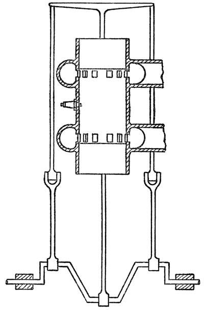
FIG. 52.—THE JUNKER ENGINE IN WHICH TWO PISTONS RECIPROCATE TOWARD AND AWAY FROM EACH OTHER
An interesting modification of the Diesel engine is the Junker engine (Figure 52) in which the cylinder consists of a tube open at each end. In this there are two pistons which reciprocate toward and away from each other. Air is compressed between them as they approach each other and fuel is[164] injected into this air, ignites and forces them apart. Both pistons are connected to the same crank shaft, one pushing down and the other pulling up. The pulling piston has a yoke on the end of the piston rod from which a pair of connecting rods run down at either side of the cylinder to a pair of cranks on the crank shaft. Between these cranks on the opposite side of the shaft is the crank to which the pushing piston is connected. The advantages of this arrangement are that the moving masses are perfectly balanced, the construction of the cylinder is very simple and especially adapted to high pressures, and the reaction of the gases, instead of being directed against a fixed part of the engine, is directed against a moving piston, thus reducing the strain on the structure. Of course the power is not doubled or increased, because each piston moves only half as far as it would for a given expansion of gas were it operating in a cylinder closed by a cylinder head.
The efficiency of Diesel engines, although greater than that of the gas and gasoline engines, is still very low. The semi-Diesel will yield about 30 per cent of the energy in the fuel, the Junker engine about 34 per cent, and the best Diesel, four-cycle engine in large units, about 36 per cent. This is a wonderfully high efficiency compared with that of a locomotive, and yet it seems pitiably low when we consider that nearly two-thirds of the energy stored in the fuel is thrown away.
SILENCING THE NOISY EXHAUST
The waste of energy is clearly evident in the exhaust pipe of an internal combustion engine. The gases after doing their work on the piston rush out[165] with such velocity as to produce a sharp explosive sound. The noise of the exhaust is highly objectionable in automobiles and must be overcome, but instead of utilizing the boisterous energy of the escaping gases and getting a little more useful work out of them, means are provided for hushing their noise. This is done by passing them through a series of baffles which reduces the pressure of the gases before they are discharged into the atmosphere. By letting the gases expand gradually instead of bursting suddenly into the atmosphere the noise of the discharge is reduced. However, this must not be done at the expense of the engine power. Unless the gases pass quickly through the muffler they will choke and retard the exhaust and make the engine do useless work in driving them through. Even the best of mufflers will use up nearly 5 per cent of the engine power. The energy that escapes at the exhaust is not the only loss. All the heat that radiates from the engine represents just so much wasted energy. In our water and air-cooled systems we deliberately abstract heat from the burning gases and throw it away. If we had materials that would stand the intense heat of burning gases and enable us to conserve all the heat developed in the cylinder we could use our fuels much more economically.
Many attempts have been made to utilize the wasted heat of internal combustion engines, but they have not met with any considerable degree of success, with the exception of the invention of William Joseph Still. This engine, which was the result of many years of patient work, was first made public in a paper read before the Royal Society of Arts in London, May 26, 1919, and when it was shown[166] that the new engine had developed an efficiency of 38 to 41 per cent it was realized that here was a remarkable advance over any other machine for turning heat into power.
COMBINED STEAM AND OIL ENGINE
The Still engine is a combined steam and gas or oil engine. The heat that is ordinarily thrown away in the water jacket and in the exhaust is utilized to produce steam, and this steam is employed to return the piston to the top of the cylinder after the gases generated by the combustion of fuel have driven it down. While in previous experiments some steam had been developed from the exhaust gases it had not been found possible to generate steam in the water jacket because of the low temperature that had to be maintained. In the standard internal combustion engine the cylinder walls are made of cast iron, thick enough to withstand the heavy pressures to which they are subjected should the charge be ignited prematurely. Around them the water circulates under practically no pressure and so the wall of the water jacket is made comparatively thin. Because of the thickness of the cylinder wall the water has to be maintained at a comparatively low temperature so as to keep the interior of the cylinder from growing too hot. In the Still engine the cylinder wall is from one-third to one-fourth the thickness of the standard cylinder wall, while the water-jacket wall is of thick steel. The cylinder wall is formed with ribs which extend to the water-jacket wall, so that the latter will take care of any excessive loads due to premature ignition. Figure 53 shows how the cylinder and jacket of the Still engine compare with those of the ordinary motor. The[167] thin cylinder wall and the ribs furnish a far better conduction of heat to the water which circulates between the ribs. The necessary cooling of the cylinder can be maintained with water at a much higher temperature than in the ordinary engine.
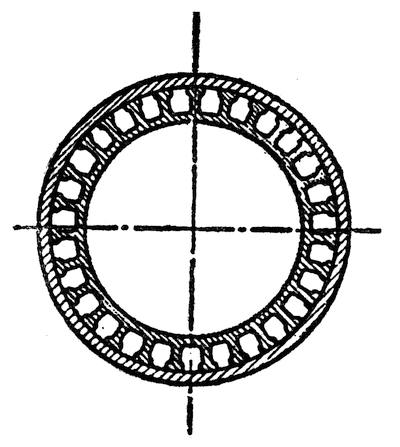
FIG. 53.—SECTION THROUGH THE CYLINDER AND WATER JACKET OF THE STILL ENGINE
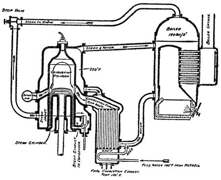
FIG. 54.—DIAGRAMMATIC VIEW OF THE STILL ENGINE
A diagrammatic representation of a Still engine of the two-cycle heavy-oil type is shown in Figure 54. This is shown with an auxiliary boiler heated by an oil burner. The piston of this engine has a sleeve which fits into an annular steam cylinder. The latter is an extension of the combustion cylinder. Surrounding the steam and combustion cylinders are the steam and water jackets. The drawing shows the piston at the end of its downward stroke, having just been driven down by the gases of combustion. In this position a scavenging-air port at the left is uncovered and the burnt gases are swept out by a blast of air, passing out of the exhaust. This consists of a bank of tubes or flues which pass through a water heater. The gases leave the cylinder with a temperature of 900 degrees Fahrenheit and they issue from the exhaust with a final temperature of only 150 degrees Fahrenheit. Steam now enters the annular steam cylinder from the steam jacket, through the port shown at the lower right-hand side, forcing the piston up and compressing the charge of air in the cylinder. Then oil is sprayed in through a nozzle, not shown in the drawing, and is ignited by the heat of the compressed air as in a Diesel engine and the piston is driven down again by the gases of the combustion. The water surrounding the combustion cylinder comes from the lower part of the boiler and flows by the exhaust flues. It is maintained at a temperature of 350 degrees in the water jacket, and here is turned[169] into steam by the heat of the combustion. Thence it passes into the steam dome of the boiler. On the downward stroke of the piston a slide valve, shown at the lower right-hand side, moves down and connects the steam port with an exhaust port through which the steam flows out into a condenser. Water from the hot well of the condenser enters the system at the combustion exhaust. The arrows show the course of the steam and water and the temperature at various points is given. As may be noted there are two systems of steam and water circulation: one from the bottom of the boiler through combustion exhaust heater to the water jacket and back to the top of the boiler; and the other from the steam dome of the boiler to the steam jacket, to the steam cylinder, to the steam exhaust, to the condenser and back again from the condenser into the combustion exhaust heater, whence it enters the boiler by way of the water jacket.
LATENT HEAT
When water turns into steam a certain amount of heat is absorbed, which does not show in the thermometer. This is known as latent heat. If cold water is placed in a kettle and is then heated the thermometer will gradually rise until the water reaches the boiling point. Then there will be no further rise of temperature, although heat is still applied to the kettle, until all the water is turned into steam, after which the thermometer will begin to show a rise of temperature, showing that the steam is beginning to grow sensibly hotter. In the engine, shown in Figure 54, a boiler pressure of 120 pounds gauge pressure is maintained, and therefore water will not boil until it reaches 350 degrees Fahrenheit.[170] The water in the water jacket registers 350 degrees and is therefore far hotter than it could possibly be in the open atmosphere. However, the heat from the combustion does not raise the temperature of the water, but expends its energy in converting the water into steam. The cylinder wall is kept at a temperature of at least 350 degrees all the time, so that the air that enters the cylinder gathers heat from the cylinder as well as from its own compression, and its temperature at the end of the compression stroke is higher than it would be in a cold cylinder, thereby insuring the ignition of the fuel when it is sprayed in.
The Still engine can also be used as a common gasoline or gas engine of either two or four cycle and the efficiency in such types is from 31 to 33 per cent. This is much better than the best airplane engines, which show an efficiency under 27 per cent. Although 41 per cent for the best Still heavy-oil engine is a remarkable accomplishment, yet it does not begin to compare with the efficiency of the best water turbines and Pelton wheels, which turn into useful power from 75 to 87 per cent of the kinetic energy in the water that drives them.
CHAPTER XI
WHEN COAL AND OIL ARE EXHAUSTED
IN PREVIOUS chapters we have indulged in a great deal of historic retrospect. It may be well at this point, while we are dealing with the subject of power, to look into the future and the prospects that it holds out to us.
It was about fifty thousand years ago, according to conservative estimates, that primitive man first began to use tools, and he managed to exist and thrive and develop to a very high degree of civilization during practically the whole of that period without touching the stores of energy that lay beneath his feet. It was only yesterday that the steam engine was invented, and when it was discovered how to turn heat into work and what a wealth of power was stored up in the deposits of coal there started a lavish and profligate squandering of the precious heritage of the Carboniferous era. The fossilized vegetation of by-gone ages is now employed to drive our locomotives and steamships, to turn our factory wheels, to extract metals from the ore and help us shape them according to our needs and desires, to convert iron into steel and to heat and light our houses. We all know that there is a limited supply of coal in the world and that some day the stores will be exhausted, yet we go on using larger quantities of the fuel each year.
For the last century our demands for coal have been doubling every ten years, until to-day the world is using about 1,200 million long tons per year. It is conservatively estimated that if our demands for coal do not increase there is enough left in the whole world within a mile of the surface to last 1,500 years. Fortunately this country is better supplied than many others, and it is probable that we can get along on our present rations for 2,000 years. England, however, faces exhaustion of her coal supplies within two hundred years.
After living fifty millenniums on earth as a being clearly superior to other animals, man comes into an inheritance which he squanders in one or at most two millenniums. It is not creditable to our civilization that we have taken no precautions to ration out this precious store of fuel.
OUR WASTE OF FUEL
As was shown in a previous chapter, we utilize very little of the energy in coal. Our steam railroads squander from 94 to 96 per cent of the coal they burn and our best turbine power plants throw away about 80 per cent. The coal we burn in domestic furnaces is most wastefully squandered. Maybe we shall learn how to use the energy in coal more efficiently and make it last longer, but eventually it will all be gone and then what are we going to do?
Of the other fuels available, petroleum takes the leading place, but we are hardly more economical in our use of this fuel and our oil supplies are diminishing much more rapidly than the stores of coal. In 1919 the United States produced 376,000,000 barrels of oil and consumed 418,000,000 barrels,[173] having had to draw on Mexico for 42,000,000 barrels. Natural gas cannot last much longer and peat bogs are estimated at about half of one per cent of the coal supplies. Where shall we turn for heat and power when all these stores of energy are gone?
It has been estimated that the water powers of the earth, if fully developed, would probably supply about half of the energy that we now get out of coal. This is a never-failing supply of energy, and no doubt before we have begun to scrape the bottom of our coal magazines every river on earth that is capable of turning a wheel will be doing so to the limit of its capacity. Then there will be a readjustment of the manufacturing centers of the earth and remote regions such as Iceland, for instance, which has more available water power than Switzerland, will hum with machinery, while such countries as Great Britain, which is relatively poor in water powers, will have to give up manufacture and revert to agricultural pursuits.
But are there not other powers that can be used? If we could capture all the energy of the winds we should have ample power to do all the work that is now done on earth with a large margin to spare. It has been estimated that the winds contain 5,000 times as much energy as is obtained from coal, but how may we capture so fickle a power as the wind. It is so variable, sometimes exerting enough power to lift houses from their foundations and uproot giant trees, and again sinking to an absolute calm. In some places wind power is turned into electricity and then stored up in batteries; but the cost of doing this is high and at present uneconomical.
“BLUE COAL”
The ocean Is a vast storehouse of energy. The quiet but powerful rise and fall of ocean tides, and the tremendous energy of ocean waves, have been looked upon with envy by engineers. All sorts of schemes have been devised for capturing a part of this energy and putting it into the service of man. Water power has been aptly called “white coal” and ocean power “blue coal.” Wave energy is but another form of wind energy and hence just as fickle. There is plenty of power to be had, but it is a costly matter to build a power plant on the shores of the ocean and any day a storm may arise which will dash the machinery to pieces and sweep away the whole plant or convert it into a pile of wreckage. In a few places, however, Nature has provided a plant which the ocean has been unable to destroy and man has adopted the plant to furnish him with power. There is a rocky cave on the California coast which is exposed to the ocean swells. As the swells sweep into the cave they compress the air therein and this compressed air is trapped in a reservoir. Then the air that has been pumped by the ocean is put to useful work. There are similar caves on other rocky coasts which could be made to deliver power when coal becomes scarce and it becomes commercially practicable to exploit them, but the amount of power they would furnish would be a mere drop in the bucket.
SETTING TIDES TO WORK
The ocean tides are also immensely powerful, but the rise and fall of the water is so slight and so gradual in most places that an enormous plant is[175] required to obtain any appreciable amount of power. In certain regions, however, tidal power is actually in use to-day. At high tide water flows into a large basin and at the ebb of the tide the outflow of the basin operates a water wheel or turbine. Power can be obtained while the basin is filling as well as while it is emptying. One serious objection to this plan is that the turbine operates intermittently and at irregular intervals, sometimes by day and sometimes by night, depending upon the tide. However, tide mills need not be exposed to the fury of ocean storms as are plants that seek to employ the power of ocean waves. In certain localities the conformation of the coast is such as to accumulate the tidal flow and produce enormous differences of level between ebb and flood tide. In the Bay of Fundy, for instance, the tide rises seventy feet and an appreciable amount of power could be obtained from the flow of water into and out of the bay. If a sea-level canal were dug across the Isthmus of Panama there would be a flow of water back and forth through it because the tides at the Pacific side have a rise and fall of only two feet while on the Atlantic side the tide rises twenty-two feet. Some power might be obtained from the tidal flow through this canal, but a fall of twenty feet in fifty miles would not produce a very swift current.
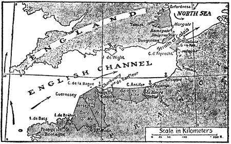
FIG. 55.—THE ESNAULT PELTERIE PLAN OF UTILIZING TIDAL POWER IN THE ENGLISH CHANNEL
If tidal power is to be utilized at all it must be done on a grand scale. A French engineer, R. Esnault Pelterie, has proposed a vast tidal power system in the English channel where the tide rises high. (See map Fig. 55.) The plan is a most ambitious one, but the power that could be obtained is enormous. He proposes to build concrete dikes across the channel at the Straits of Calais inclosing a large basin about twenty miles wide and turbines would be operated by the flow of water into and out of this basin. Of course locks would have to be provided to permit the passage of ships through the basin. Other and larger basins could be formed by walling off the estuary of the Thames and the bay of the Seine on the French coast. The Gulf of St. Malo could be inclosed by running a dike from Cape La Hague to the island of Guernsey and thence to the mouth of the Trieux. These basins would furnish a minimum of 800 horsepower for each square mile, hence the basin across the Straits of Calais alone would furnish nearly half a million horsepower while the Gulf of St. Malo would furnish about a quarter of the power that France now uses in her industries. The first cost of the installation would be heavy, but there would be no expense[177] for fuel and the supply of power would be endless. It has been proposed to dam the estuary of the Severn (England) where the spring tides rise thirty feet, and it has been estimated that half a million horsepower would be developed. Part of the power would be used to pump water into an elevated reservoir which would serve as a storage battery, so that when the tidal plant was idle because of the turn of the tide, water flowing out of the reservoir would operate an auxiliary plant, thereby furnishing a continuous supply of power.
POWER FROM SUNSHINE
With the exception of the tides all the energy we use on earth comes from the sun. It is the sun’s energy that is stored in coal beds and oil fields; it is the sun’s energy that raises water from the ocean to the tops of our mountains; it is the sun’s energy that makes the winds blow, and through them disturbs the surface of the ocean, and even the tides owe a part of their energy to the attraction of the sun. Why can we not utilize the energy of the sun directly, instead of at second hand? In the sunshine that beats upon the earth there is seventy-thousand times as much energy as we now obtain from coal. Unfortunately the energy of the sun is so widely dispersed that it cannot be used economically except in a very few places where clouds do not often interrupt the direct passage of the rays to the earth’s surface.
Near Cairo, Egypt, there is a plant erected by an American inventor, Mr. Frank Shuman, which develops about fifty horsepower. This consists of a series of five huge trough-shaped mirrors that focus the sun’s rays upon boilers and thus generate[178] low pressure steam. The mirrors measure 13 feet in width and 304 feet in length and these are mounted on a light steel framework with their axes running north and south so that they may be turned from east to west to follow the course of the sun across the sky. In order to prevent the mirrors from shading each other in the early morning and late afternoon they are set twenty-five feet apart. Mirrors are made of thin sheets of window glass, silvered at the back. The troughs are parabolic in cross section and at the focus of each is hung a tubular boiler painted black to absorb the heat rays. The five boilers feed a common steam reservoir from which steam is fed to a pump. This pump raises about 6,000 gallons of water per minute, which is used for irrigating purposes. Of course at night the supply of energy is cut off and on cloudy or rainy days no steam is generated, but such days are few in the region of Cairo, and continuous operation is not essential to the operation of irrigating systems.
There are localities in Africa, Asia Minor, and even in the United States where the lack of water and the pitiless rays of the sun have turned vast regions into deserts. Here the very rays which have parched vegetation may be utilized to pump water over the thirsty lands and convert them into rich agricultural regions.
There is another mighty source of power in the internal heat of the earth. Here and there all over the earth are vent holes through which the pent-up energy makes its escape in the form of steam, gases, or molten lava. There is no question as to the enormous stores of energy in active volcanoes, and as we appreciate the value of heat energy our eyes[179] turn covetously to these great chimneys of the subterranean furnaces.
HARNESSING VOLCANOES
It seems like the height of daring to attempt to harness the volcanoes, and yet there is a plant in Italy which utilizes volcanic energy and develops useful power from it. At Volterra, in the province of Tuscany, there is a volcanic region where jets of very hot steam issue from cracks in the ground. These steam jets, known as soffioni, are laden with gases and mineral matter. For many years the boric acid that they contain was abstracted from them, but the steam was allowed to escape. In some few instances it was piped into houses and used for domestic heating. In 1908 an attempt was made to convert the energy of the steam into useful power. Holes were bored into the earth and steam of a temperature of 302 degrees Fahrenheit came up the pipes. This steam was applied directly to a forty horsepower steam engine, and for the first time volcanic heat was set to work. The steam, however, contained so many impurities that it was impracticable to use it directly in the engine. The valves and cylinders were soon clogged with deposits of boric acid. Then instead of trying to obtain power directly from the steam, the latter was used to heat a boiler in which pure steam was generated. This plan proved perfectly practical and a 300 horsepower condensing steam turbine was driven by the energy thus obtained indirectly from volcanic heat. This power was converted into electricity and the power was transmitted to the surrounding villages. After the World War broke out and Italy began to feel the shortage of fuel, the[180] price of coal having risen to $50 per ton, the use of volcanic power was extended. A 3,000 kilowatt plant was installed and electric current was transmitted to Florence, Leghorn, Volterra, and other towns of Tuscany. The exhaust steam from the boilers was utilized in the boric acid industries.
Other projects for utilizing the internal heat of the earth have been given serious consideration in Italy. Near Naples there is the dormant volcano, Solfatara, the crater of which is filled with a sea of very hot mud underlying a cool thin crust of earth. Holes bored into this mud to a depth of a few feet send forth steam hot enough to do useful work and a plan to utilize this store of energy is under way.
POWER FROM THE CORE OF THE EARTH
There are regions where the ground is red-hot at a depth of a hundred feet. While there is no water present to furnish steam, it is a simple matter to sink a water pipe down to the heated earth and then, around this pipe, to drive a ring of smaller pipes through which steam may find its way up to the top and be fed either into water heaters or directly into steam engines. In fact it has been suggested that such a scheme might be used almost anywhere. If we bore into the earth, we find that the temperature grows higher the deeper we go. The rate of increase of temperature varies with different localities, but it is very evident that anywhere on earth temperatures that will give a steam pressure of ten or more pounds per square inch can be obtained if we dig down far enough, and when we find it worth while to do so we shall probably riddle the earth’s crust with perforations[181] through which water will be sent down to the subterranean furnaces and it will return to us laden with heat energy.
After all, we shall not be plunged into dire want when our stores of coal are exhausted. There will be other sources of power to draw upon, most of which will be inexhaustible. Furthermore, we have recently discovered in atoms of matter stores of energy incomparably greater than any that have heretofore been used to work the will of man. How to utilize this energy we have not yet learned, but the energy is there, and no doubt, some day, probably long before coal takes its place in museum collections, we shall be possessed of a new slave, far more powerful than that which has served us so far.
CHAPTER XII
INVASION OF THE SEA
THE POSSIBILITY that the wind was the first inanimate power utilized by man, has already been referred to. There are records of the use of sailing vessels in Egypt that date as far back as 6,000 years before Christ. Navigators of that early date, however, could hardly claim to have mastered the wind. They merely used wind power when the wind was disposed to help them. If the winds were adverse, they had no recourse other than to furl their sail, step the mast and depend upon oars to propel them to the desired port. It was not until thousands of years later that primitive mariners learned how to tack and pursue a zigzag course against the wind. When this knowledge was acquired we do not know, but it is certain that the Phœnicians, who rounded the continent of Africa 1,200 years before Christ, knew how to make use of the power of opposing winds. Of course they could not explain how it was that a breeze could be made to drive a vessel in a direction across and even opposed to that in which it was blowing. In order to understand this apparent paradox ourselves, we must go back to the very elements of mechanics.
ELEMENTARY MECHANICS
The popular conception of force is something that produces motion, but its true definition is “that[183] which tends to produce or resist motion.” There are forces in existence when there is no motion. When you hold a weight in your hand there is a force tending to pull the weight to the earth, but this force is opposed by an equal force exerted by your muscles in holding up the weight. There is no motion because the two forces are perfectly balanced. If they were unbalanced, there would be motion in the direction of the greater force. If the pull of the arm is greater than that of gravity, the weight will be lifted, and if the weight is too heavy for the arm to support, it will go down despite muscular efforts to prevent it. In one case the force of gravity will endeavor to destroy motion by opposing the lift of the arm, and in the other case the arm will endeavor to resist motion by opposing the pull of gravity. A book on a table is motionless and yet it is acted upon by two forces which are opposed to each other and hence balanced. The table furnishes a force which resists and balances the force exerted by gravity. If the book were heavy enough, in other words, if the force directed downward were great enough, the table would be crushed.
When two forces are in perfect balance they must be equal and opposite. Unless the directions of the two forces are exactly opposite, there will be motion in some new direction. Suppose we use an apparatus such as shown in Fig. 56 to study the result of three coacting forces. It consists of a T-shaped frame with a pulley P at each end of the cross arm. These pulleys turn very freely on their axes, so that we need not be concerned with any appreciable amount of friction. Two fine cords running over these pulleys are knotted at O to a third[184] short cord. Each cord is provided with a hook on which weights may be hung. Now if we put a pound weight on each cord the two A and B will raise the weight C until the angles between the cords at O are all equal. In other words each force of one pound is balanced by two other forces of one pound each pulling at an angle of 120 degrees to it and to each other. If we put a 3-pound weight at A, a 4-pound weight at B and a 5-pound weight at C, the cords will come to rest in the position shown in Fig. 57. The weight B being heavier than weight A will pull the knot O to the right until the angle between the cords running to these weights is a right angle.
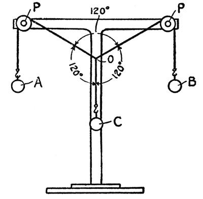
FIG. 56.—BALANCED FORCES—EQUAL WEIGHTS
PARALLELOGRAM OF FORCES
Although a force is something that cannot be pictured it can be represented graphically by means of a line, letting the direction of the line represent the direction of the force and the length of the line the strength of the force. In Figure 58 we may[185] measure off 3 inches from O to a to indicate the 3-pound force and 4 inches from O to b to represent the 4-pound force and 5 inches from O to c to represent the 5-pound force. Now if from a a line is drawn parallel to O b and from b a line is drawn parallel to O a we shall have a parallelogram a O b d, and if we extend the line O c it will bisect the parallelogram, running diagonally from O to d, and this diagonal will be found to measure exactly 5 inches which represents the 5-pound force. This is what is known as the parallelogram of forces. It shows us the resultant of any two forces that are not directly opposite and it gives us the direction as well as the strength or magnitude of this resultant. It is only because we happen to choose the forces 3, 4 and 5 that the angle at O is a right angle. In Figure 59, where the forces are all equal, our parallelogram is lozenge-shaped and the line O d is just as long as the line O a and O b, showing that its magnitude is the same as that of the two forces that balanced it.
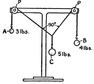
FIG. 57.—BALANCED FORCES—UNEQUAL WEIGHTS
The greater the angle between the two lifting forces the less weight can they lift. If two men are carrying a ten-pound satchel, each will be lifting five pounds, if the pull is directly upward; but this is a rather inconvenient way of carrying the bag and usually they pull at a slight angle from the vertical, and so each must carry more than half the weight. If they move so far apart that the angle between them is more than 120 degrees, each will be carrying more than the full weight of the bag.
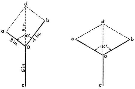
FIGS. 58 AND 59.—PARALLELOGRAMS OF FORCES
SAILING AGAINST THE WIND
Now that we know something about the parallelogram of forces we may return to the problem of sailing across and against the wind. In Fig. 60 we are looking down on the deck of a ship and the wind is represented by the arrow. The dotted line A B represents the direction in which the boat is traveling and the line C D represents the plane of a sail. If the line E F represents the magnitude and[187] direction of the force of the wind at the center of the sail, then we can tell how much pressure is being exerted directly against the sail, by drawing the line g F perpendicular to the sail and completing the parallelogram by drawing from E a line parallel to the sail intersecting g F at G and another line parallel to g F intersecting the plane of the sail at H. Then the length of the line G F represents the pressure against the sail. If the line G F is half as long as the line E F, then only half of the force of the wind is exerted in the direction G F. In other words, a wind pressure of one pound per square foot blowing in the direction of G F will do as much work as two pounds in the direction E F. The force of the wind has been broken up into two “components,” one (G F) at right angles to the sail, and the other (H F) edgewise to the plane, and of course the latter has no effect upon the propulsion of the boat.
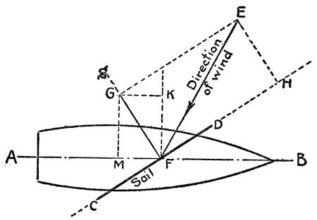
FIG. 60.—FORCES THAT MOVE A SAILBOAT
If there were nothing to prevent it, the boat would sail in the direction G F; but the keel of the boat[188] offers resistance to motion in this direction, and we must construct another parallelogram around the force G F to find the magnitude of the force exerted in the direction A B. The line K F is drawn at right angles to A B, and then the parallelogram is completed by drawing a line from G to K parallel to the line A B and another from G to M parallel to K F. We have then resolved to force G F into two components M F and K F. The former tends to push the boat along its course while the latter tends to make it drift to leeward. The length of the line M F is little more than a quarter of the length of the wind force E F and the leeward acting force K F is actually considerably greater than the forward acting force M F. Even with a deep keel there will be some drift to leeward. This is corrected by means of the rudder of the ship which is turned to head the ship further into the wind so that although the boat does not actually travel in the direction of its axis it may be made to travel along the course A B. Of course the boat cannot sail directly against the wind, but it can accomplish the same result by tacking alternately to port and starboard so that eventually it can reach a port that lies in the direction from which the wind comes.
THE SPEEDY CLIPPER
Before the advent of the steamship, sailing vessels were developed to a high degree of efficiency. The speedy clippers of 1816 to 1845 used to cross the Atlantic at an average speed of 6 to 9 miles per hour and sometimes even better, which compares favorably with a common steam freighter of to-day. The largest sailing vessel ever built was the Thomas W. Lawson, a seven-masted schooner. She[189] was launched in 1902, but foundered in 1907 off the Scilly Islands. This great ship was a steel vessel 395 feet long, with a displacement of 10,000 tons and a cargo capacity of 7,500 tons. She had a sail spread of 40,617 feet.
FROM OARS TO PROPELLERS
Although a century has elapsed since the first steam-driven vessel made its way across the Atlantic Ocean, sails have been as yet by no means swept off the face of the sea. Nevertheless, even when sailing vessels had no competitors they did not furnish a perfectly satisfactory means of transportation. The fickleness of wind power was felt in this application as well as in that of windmills, and inventors racked their brains for some more certain means of propelling ships. Naturally, when the steam engine was a proven success, efforts were made to apply this newly discovered power to ships. How to make steam drive a ship was a problem. At first it was proposed to use a system of oars which would be moved back and forth in imitation of oarsmen and John Fitch’s first steamboat in 1786 was driven by a set of paddles operated in a manner similar to that of paddling a canoe. It was a very natural evolution from oars to paddle wheel, which consists of a series of oars mounted in a wheel so that they will come into play one after the other. The propeller, although not invented by Col. John Stevens (as has been popularly supposed), was first applied by him to steam navigation when he constructed a small steamboat on the Hudson River in 1804. But the simplicity of the paddle wheel and its high efficiency, particularly in quiet harbors and shallow inland waters, gave it preference over the propeller.[190] In rough seas, however, the paddle wheel was far from ideal. It was too easily broken by heavy waves and between 1855 and 1865 the propeller displaced it completely for ocean-going vessels.
WATER JET PROPULSION
Another curious form of propulsion, which dates back to the eighteenth century and is still periodically revived by inventors, is the water jet. The idea was to have the engine operate a pump which would drive a stream of water out of the stern of the boat and drive the boat by reaction. The British Government actually built two jet-propelled steamers. One of them, called the Waterwitch, was a 1,100-ton vessel and the other, the Squirt, was a small torpedo boat. The latter attained a speed of but twelve knots while a sister ship of the same steam power driven by a propeller attained a speed of seventeen knots. The Waterwitch was even less efficient. Some years ago experimental water-jet vessels were built in New York in which a jet only ⅝ inch in diameter with a pressure of 2,500 pounds per square inch was used, but the experiment proved a failure. The propelling force of a jet is the reaction of the stream of water against the orifice from which it issues. The action is just like Hero’s reaction steam turbine referred to on page 143. The propulsion would be the same were the jet discharged in the open air or in a vacuum or against a solid stone wall.
WATER AND AIR RESISTANCE
It takes very little power to move a boat slowly because the resistance that has to be overcome is merely the parting of the water at the bow and[191] closing in of the water at the stern and the skin friction along the sides of the hull. In addition to this there is a similar resistance offered by the air. At very low speeds the resistances of the water and the air are practically negligible. In perfectly quiet water with no air stirring the pull of a cord will move a ship weighing hundreds of tons, but the motion will be very slow indeed. Unfortunately the speed of a ship does not increase directly in proportion to the power that drives it. Doubling the power does not double the speed. If it takes ten horsepower to drive a vessel at a speed of ten knots it will take not 2 but 2³ or 8 times as much power to drive it at a speed of twenty knots. In other words, the horsepower goes up as the cube of the speed. This is an average condition for ordinary speeds. For very high speeds the horsepower may have to be increased as the 4th and even the 5th power of the speed. The shape of the bow and the stern is of utmost importance. The parting and displacement of the water at the bow and the replacement at the stern produce waves and the forming of these waves represents so much wasted energy. The swell that is kicked up by a steamer is evidence of power uselessly expended. Much of this loss can be overcome by careful design of the ship’s lines. A vessel that kicks up a high bow wave—one that sails with a “bone in its teeth”—may present a very pleasing spectacle and may seem to be traveling at high speed, but the best designed vessel—the one that slips through the water with no fuss—is much more economical of power. It is easy to understand that the bow must be carefully designed to cut through the water, but it is not so apparent that the stern must also be shaped to permit the water[192] to flow in readily and fill in the void behind the ship. If the stern is not carefully shaped, there will be a serious drag on the vessel. The skin friction of the vessel is greatly increased by fouling of the hull with marine growths. At high speeds the wind pressure on the superstructure is considerable. Every spar and line adds its quota. A boat that is traveling in still air at a speed of twenty-two knots or twenty-five miles per hour is encountering the equivalent of a twenty-five mile wind which will exert a pressure of over three pounds per square foot of frontage.
FLYING ON WATER
Instead of cutting through the water modern speed boats are designed to ride over it. The boats have flat bottoms which are arranged as a series of flat planes known as hydroplanes. These planes form steps and are set at such an angle as to make the boat rise up on the water in the same way that a kite rises in the air. The higher the speed the higher the boat rises so that at full speed it skims on the surface. Hence there is comparatively little power wasted in displacing the water. Some of these boats are driven by air propellers so that water resistance to the propeller gear is avoided. These hydroplanes (they must not be confused with hydroaeroplanes) almost fly over the water.
FIRST OCEAN STEAMER
It was in 1807 that Robert Fulton built the Clermont and established steam navigation by running a regular service between New York and Albany, and it was twelve years later that the Atlantic Ocean was first crossed by a steam-driven vessel. It was an American vessel, the Savannah, that[193] made the trip. She was a 380-ton ship equipped with steam power to help her along when the wind failed. Seventy-five tons of coal and twenty-five cords of kindling wood were taken aboard to feed her furnace. This was thought to be ample for the voyage, but before the trip was completed the fuel was all gone. The log of the Savannah bears this entry the night before sighting the Irish coast: “2 A. M. Calm. No cole to get up steam.” However the captain did raise steam just before reaching Kinsale, Ireland, by burning wood. Watchers ashore beholding the smoke issuing from her stack were convinced that the vessel was afire and boats were dispatched to the rescue. The Savannah made the trip from Savannah to Kinsale in 23 days and was under steam propulsion for only 80 hours of this time.
Regular trans-Atlantic steam service was not inaugurated until 1838, but for many decades steamers were equipped with sails to assist them when the wind was favorable.
The most notable of early steamships was the Great Eastern, a combined screw and paddle-wheel ship, 692 feet long, built in 1858. She held the record for size until 1899 when the Oceanic, 704 feet long, was put into service. At present the Leviathan, formerly the Vaterland, holds the record with a length of 920 feet. It is difficult to judge of the size of a vessel out on the open water. If the Leviathan were placed in Broadway, New York, she would span nearly four blocks. Because of her 100-foot beam she would be too wide to be wedged in between the skyscrapers that border lower Broadway. If she were set up on end she would tower 158 feet above the pinnacle of the Woolworth Building. Her power plant consists of four turbines which total[194] 90,000 horsepower and the huge vessel is driven at a speed of 25.8 knots or nearly thirty miles per hour.
The wonder of these huge floating structures lies not merely in their gigantic proportions but in the fact that they are able to weather the terrific wrenching strains of heavy ocean storms. A skyscraper is built to withstand only the steady and direct pull of gravity and the variable thrust of the wind which, except in western cyclones, seldom amounts to thirty pounds per square foot. Bridge building is more difficult because of the leverage of the parts overhanging the foundations. Wind pressures must be calculated and also the live load of objects moving over the structure. In naval architecture enter the problems of building construction combined with those of bridge building, complicated by the fact that there is no fixed foundation for the structure to rest upon. At one moment a ship may be spanning a trough in the seas and at the next it may be seesawing over the crest of the wave. Of course the bottom of the boat is seldom if ever out of the water and a certain amount of support is provided throughout the length of the vessel, but the ship is subjected to the strains of a cantilever bridge when she is passing over a wave, and to the strains of a truss bridge when spanning a wave trough. These strains are increased by the fact that the structure is in constant motion. A certain degree of flexibility is demanded of the materials which go into the structure and of the joints between the frame members.
BOATS OF ARTIFICIAL STONE
Originally wood was used for the hulls of ships; then between 1845 and 1855 iron supplanted wood,[195] Between 1875 and 1885 steel supplanted iron and to-day efforts are being made to supplant steel with concrete. The advantages offered by concrete are cheapness and speed of construction. The first large vessel built of this material was the Faith, an 8,000-ton ship. This boat stood up very well in heavy weather despite the rigidity of her structure. It is doubtful, however, that a large boat comparable in size to the Leviathan could weather a severe ocean storm.
The proposal to build ships of cement created almost as much of a popular sensation as did the first iron boat. Although the public had accepted iron and then steel as a perfectly proper material for shipbuilding, concrete seemed too much like stone and it did not seem possible that artificial stone could be made to float. They did not realize that a cubic foot of steel weighs four times as much as the same volume of concrete. Of course concrete does not begin to have the tensile strength of steel and consequently the walls of a concrete ship must be made relatively thick. For this reason a concrete vessel is heavier than a steel vessel. She draws more water and requires a larger power plant, and because of her greater mass she is not so readily maneuvered.
SUBMARINE NAVIGATION
As was explained in Chapter VI, a body will float only so long as it is lighter than the volume of water it displaces. It is almost impossible to keep a body suspended in water unless some portion of it is exposed above the surface. If it starts sinking it will keep on going down until it reaches the bottom of the sea. There is a popular notion that at great depths water becomes dense enough to float[196] solid iron, but water is practically incompressible and its density at a depth of five miles is only slightly greater than that at the surface. An object must therefore either float on the surface or sink to the bottom, unless its weight is exactly equal to the difference between the upward pressure of the water under it and the downward pressure of the water above it. Such an ideal balance it is practically impossible to obtain unless the object itself is compressible.
How then can a submarine navigate under water without sinking to the bottom?
A SUBMARINE OF THE SEVENTEENTH CENTURY
The first solution to this problem dates back to the seventeenth century. Doctor Cornelius Van Drebel, a Netherlander, who was a guest at the court of King James I of England, built three submarines between 1620 and 1624. These were rowboats covered over with a water-tight deck and propelled by twelve oarsmen. It is recorded that Van Drebel discovered a means of holding the boats submerged by observing some fishermen towing baskets full of fish up the Thames. The barks to which the baskets were attached by cables were weighted down by the load they were towing, but when the cables slackened the boats rose a little bit. Van Drebel’s method of applying this principle was evidently to attach a weight to the boat which trailed along the bottom. When the oarsmen propelled the boat, she was pulled down under the surface by the drag, but when the rowing ceased the boat would float up to the surface. King James himself is said to have made a journey of several hours’ duration in one these boats, which was kept at a depth of[197] twelve to fifteen feet below the surface. Progress must have been very slow because the range of the submarine was given as five or six miles.
During the Revolutionary War David Bushnell built a submarine with which attempts were made to sink a British frigate lying in the Hudson River. This submarine was driven by a hand-operated screw propeller. The boat was provided with water ballast tanks, and by pressing a valve with one foot he could let in water enough to submerge the boat while with the other foot he could operate a pump to empty the tanks and bring the boat to the surface. When the boat was ballasted so that she would barely float, a vertical screw propeller was operated to raise or lower her as much as desired. A 200-pound lead weight was attached to a long cable which passed up through the bottom of the boat, and by letting out this cable the submarine could be made to rise instantly in case of an accident.
FULTON’S HAND-PROPELLED SUBMARINE
To Robert Fulton, however, belongs the credit of building the first submarine operating on the principle that is now universally used. His boat was also driven by a hand-operated screw propeller and was furnished with water tanks which could be filled or pumped out at will, but after the submarine was weighted until only the conning tower showed above water, she was submerged or raised by means of horizontal rudders or hydroplanes which could be tilted to any angle desired. Of course these rudders, like any other rudders, would not operate unless the boat were in motion. Such is the case with modern submarines. Like bicycles, they must keep on going or they will fall. If they[198] are heavy, they will fall to the bottom, and if light they will “fall” to the surface. When in motion the hydroplanes will either hold them down or lift them up according to the angle to which these horizontal rudders are tipped.
Robert Fulton’s Nautilus had a fish-shaped hull of copper plating on iron ribs and was twenty-one feet three inches long by six feet five inches at her greatest diameter. The screw propeller was operated by two men. When the boat was on the surface a sail was raised to assist in driving the boat. This sail could be folded up like a fan when it was desired to submerge.
Fulton deserves full credit for anticipating so many of the essential features of the modern submarine, but of course the Nautilus was a mere toy compared to the marvelous machines which swim under the surface of the sea to-day.
The German U-boats at the outbreak of the war were 150 feet long and could make only nine knots submerged and twelve knots on the surface, but later they grew to a length of 300 feet with a submerged speed of twelve knots and a surface speed of eighteen knots. The British in the meantime developed a submarine that was 340 feet long and had a displacement submerged of 2,700 tons as against 800 for the largest German U-boats. The speed of this big British boat is twenty-four knots on the surface and ten knots submerged.
SUBMARINES AS SURFACE BOATS
Despite their name, submarines are really surface boats. Only when necessity demands are they submerged. During the war even the U-boats did 90 per cent of their sailing on the surface. Origially[199] submarines were built primarily for submerged travel and consequently they were given the form of a fish or of a fat cigar, but such a shape was not adapted for surface sailing. Water piled up on the nose of the boat and tended to bear her down. To overcome this, submarines are now shaped more like a boat with a bow high enough to part the waves without burrowing into them.
POWER PLANT OF A SUBMARINE
The gasoline engines that were formerly used for propelling the boats have now given way to heavy oil or Diesel engines, because of the greater efficiency of these engines and the greater safety of handling heavy oil. Some submarines have been equipped with steam power plants. Such is the power used on the big British submarines above referred to. Of course any power that involves the burning of fuel can only be used on the surface. As has already been explained, an internal combustion engine burns seven to nine times as much air as oil and it would be impossible to store enough air on board to keep the engines going very long; hence they can be operated only while the hatches are open to the atmosphere.
Coupled to the shafts of the engines are dynamos which generate electricity and feed it to storage batteries. A dynamo will serve as a generator when turned by some mechanical power and on the other hand when current is fed into it, it serves as a motor, so that when traveling submerged and fuel can no longer be used, the generators are disconnected from the engines but remain connected to the propeller shafts and driven by the very current they previously stored in the batteries.
THE COLLAPSIBLE “EYE” OF THE SUBMARINE
Amidships there is a bridge from which the vessel can be navigated when on the surface and a conning tower from which she can be navigated when running awash. Most of the submerged travel is maintained at a comparatively shallow depth so that the submarine can keep an “eye” on the surface. The eye is the periscope of which there are two so that in case of damage to one the other may be used. Periscopes date back to the “Fifties” when they were used on some experimental European submarines. In the Civil War, when the river monitor Osage ran aground in the Red River, her captain, now Rear-Admiral Thomas O. Selfridge, rigged up a periscope with which he could look over the high banks of the river and direct the fire of his guns upon a Confederate force that was attacking him. This periscope consisted merely of a three-inch pipe with a hole at each end cut in opposite sides of the pipe. Small mirrors were set in the pipe so that the light coming in through the upper hole was reflected down through the pipe and out of the lower hole. This crude periscope is the same in principle as the modern submarine periscopes except that the latter are provided with lenses to gather and focus all the light possible on the eyepiece so that the operator will have a perfectly clear view. Periscopes extend fifteen to twenty feet above the roof of the conning tower. While periscopes are insignificant objects on the broad seas when a submarine is moving very slowly, they are made conspicuous by the wake of foam that follows them when the boat is traveling even at a moderate speed. For this reason during the war the Germans developed[201] a telescoping periscope which could be shot up to the surface whenever desired in order to give the commander a glimpse of his surroundings.
The submarine is submerged by letting water into the ballast tanks and then turning the hydroplanes to a diving angle. There is an after as well as a forward pair of diving rudders.
When running completely submerged the submarine is blind and solely dependent upon the chart and compass. It is impossible to see far under water. Searchlights are of no value at all. They will not make visible an object a hundred feet away. The submarine commander cannot see even the bow of the boat he is piloting. The ordinary magnetic compass will not operate when entirely incased in steel as it is in the hull of the submarine and so a gyroscope compass has to be used instead.
While the compass serves as a guide for travel in the horizontal plane the depth gauge must be watched to see that the boat does not dive too deeply. The pressure of the sea increases at the rate of 64 pounds per foot of depth. Two hundred feet below the surface the pressure amounts to about six tons on every square foot of the surface of the submarine. Few submarines can stand a greater pressure than that without being crushed or at least springing serious leaks. When coming to the surface the hydroplanes are used and if the boat is to remain on the surface water is blown out of the ballast tanks.
THE “EARS” OF A SUBMARINE
Although submarines may be blind under water they are not deaf. Sound detectors are used which enable them to locate other vessels by the throbbing of their engines or the beat of their propellers and[202] so they can avoid collisions when coming up to the surface.
Despite the perfection of the submarine the sea is still a great mystery to us. We know only its surface and its shallows. We have sounded a few deep holes and brought up samples of deep-sea life, but we have not been able to penetrate in person its profound depths and explore with our eyes and hands the world that is buried beneath its waves. Three quarters of the globe is covered by water and if we are to claim complete mastery of the earth we must find some way of descending into the heart of the ocean and exploring its deepest valleys.
CHAPTER XIII
SLIDING, ROLLING, WALKING, AND CREEPING
IN ALL forms of transportation friction plays a most important part. If there were no such thing as friction, it would be impossible for us to set an object in motion by the means that are now commonly in use, and once the object were moving it would be impossible to stop it except by bringing it up against a wall set squarely across its path.
In transportation on land friction is a much more serious bar to motion than it is in marine or aerial transportation. There are two kinds of friction that we have to contend with; sliding friction when two contacting surfaces are dragged by each other; and rolling friction when one surface rolls upon another. It is impossible to obtain two surfaces that are absolutely smooth; there are minute elevations in each that sink into minute depressions of the other like intermeshing teeth and a grinding action takes place as these microscopic inequalities are broken away. Oil reduces the friction by filling up these inequalities, but the oil itself offers a certain amount of friction just as water does along the sides of a moving ship.
ROLLING FRICTION
Rolling friction is of a different kind. The intermeshing inequalities or microscopic teeth are[204] lifted out of contact with, one another just as the teeth of gear wheels are carried out of mesh. But there is another cause of friction due to the fact that no objects are so microscopic that they do not sink into each other to some extent. A wheel is always rolling out the surface it is turning on just as a rolling pin rolls out dough. If the surface is of elastic material such as a steel rail, it springs back into place immediately after the passage of the wheel, but the wheel must constantly travel in the trough of a wave which accompanies it along the rail. There is a similar wave in the wheel itself and this ironing-out action produces heat in the wheel and the rail. It is particularly noticeable in the flexible tires of automobiles which, after a run on even a smooth road, become too hot to be grasped with the bare hand merely because of the waves of compression and decompression to which they are subjected.
Both rolling and sliding friction are increased by pressure because the depression is greater and because inequalities are brought into more intimate engagement with one another. The degree of friction also depends upon the nature of the substances in contact, but theoretically the area of contact does not make any difference. It is just as hard to push a block along a smooth surface on its edge as on its side.
PUTTING ROLLERS BETWEEN LOAD AND ROAD
As intimated in Chapter I the forerunner of the wheel was probably the roller. It was much easier to move a heavy object on rollers because rolling friction was substituted for sliding friction, but the rollers would not stay under the object; they[205] traveled only half as fast as the load they carried. To make them keep up with the load they had to be mounted on axles which were fastened either directly to the load or to a cart body on which the load was supported. Thus the wheel came to be invented, but except for the fact that it stays by its load and does not roll out from under it a common wheel is not to be compared with a roller for efficiency. To be sure, it substitutes rolling friction for sliding friction where it contacts with the road, but the friction at the axle is sliding rather than rolling. However, drawing an object on wheels is a decided improvement over sliding it along the road, for two reasons: the sliding friction at the axle is reduced to a minimum by choosing materials that will slide upon each other with comparatively little resistance, by polishing them smooth and by lubricating them. But even if these precautions were not taken there would be a distinct advantage in the use of wheels because of the relatively shorter travel at the axle than at the rim of the wheel. If a wheel is thirty inches in diameter and turns on an axle one inch in diameter, it will travel thirty times as far at the rim as it does at the axle; hence the sliding friction at the axle is far less than it would be at the point of contact with the ground, were the wheel locked so that it could not turn. But it is not necessary to have any sliding friction at the axle if we revert to the old roller system that prevailed before the day of the wheel. The axle may be considered the load and the axle bearing the road. We can then put rollers between load and road. Because the road is a circular one that travels with the load we can line it with rollers throughout its length, and the load will never lack for rollers to[206] roll upon. Thus we have the roller bearing which is so widely used in modern vehicles. Ball bearings operate on the same principle except that the balls furnish less contacting surface and are not so suitable for supporting heavy loads, as are rollers. Sliding friction is almost completely eliminated and unless heavily loaded a wheel on ball bearings will not heat even when the bearings are not lubricated.
REDUCING ROAD FRICTION
While there is little friction between a wheel and the roadway upon which it travels, the roughness of the road is a very important factor. Every time a wheel goes over a stone the entire vehicle must be lifted; this represents so much wasted energy. The advantage of the pneumatic tire lies in the fact that it absorbs small inequalities without making it necessary for the entire vehicle to rise over them. This means less load lifted and hence less work done. Large wheels are better than small ones because they do not sink so deeply into depressions and because they surmount small obstacles more readily. On a steel track the size of the wheel does not make so much difference as it does on a road because the track surface is smooth and is but little depressed by the wheel. It has been estimated that a horse can pull ten times as great a load on rails as on an ordinary macadamed road. Some years ago broad steel tracks were laid in some of our city streets for the use of horse-drawn trucks. They served very well as far as the vehicles were concerned. The road friction was reduced considerably, but the fact was overlooked that the horses needed a good friction surface under their feet. Two horses could not pull a truck along the track without[207] walking on the track and the smooth steel made such slippery footing that the tracks had to be torn out and replaced with common paving.
INCREASING TRACK FRICTION
The difference between sliding and rolling friction is well illustrated in a locomotive. The driving wheels are turned around by steam power. They must either roll or slide on the track and the load they will pull without slipping is a measure of the excess of sliding friction over rolling friction. To increase the traction or the adhesion of the locomotive to the track it is provided with a number of driving wheels. In some of our largest locomotives driving wheels are placed under the tender so as to obtain a maximum of traction.
ANCIENT LINEAGE OF THE AUTOMOBILE
When it was first proposed to substitute steam propulsion for the horse it was not realized that a rail would furnish enough traction to permit of hauling heavy loads, and some of the early locomotives that ran on rails were provided with toothed wheels that engaged in racks alongside the rails. In fact, the earliest locomotives were not built to run on rails but on ordinary roads; in other words, they were automobiles. The motor car can therefore boast of a more ancient lineage than the railroad engine. Joseph Cugnot of France is said to have built a three-wheeled steam carriage in 1769 which was so top-heavy that it upset when making a sharp turn at three miles per hour. Several steam carriages were built in England in the eighteenth century, but they were not successful. The real father of steam traction was Richard Trevithic, of Camborne,[208] Cornwall, whose first steam carriage, built in 1801, carried eight passengers. His third machine, built in 1804, was the first to run on rails. This was strictly a locomotive intended to haul cars. It ran with its load at the astonishing speed of five miles an hour. Trevithic was the first to exhaust the steam from the cylinders into the smoke-stack and thereby increase the draft through the furnace and generated steam at higher pressure.
All the early locomotives used toothed gears to turn the driving wheels until George Stephenson introduced connecting rods to drive the driving wheels direct from the pistons. George Stephenson’s “Rocket,” built in 1829, won a prize of 500 pounds in a speed contest when it established a record of 24 1-6 miles per hour. It also established the doubtful honor of being the first mechanical speed monster to exact the toll of human life. On its prize run it ran over a man and killed him.
STEPHENSON’S LINK MOTION
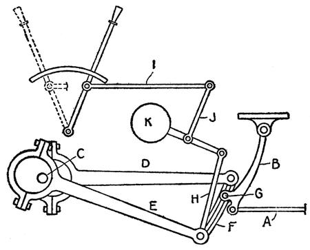
FIG. 61.—STEPHENSON’S LINK MOTION
Stephenson’s son Robert is commonly credited with the invention of an ingenious link motion, although the invention is also claimed for W. T. James of New York. We must pause a moment for a description of this ingenious link motion, because it became a standard in locomotive construction that is still in service. As explained in Chapter IX steam should be used expansively in order to obtain a maximum of efficiency. After a certain amount of steam has been admitted into the cylinder it is cut off from the boiler and it pushes the piston by its own expansion. The speed of the locomotive must be varied by varying the point of cut-off, and the direction of motion of the locomotive is reversed by reversing the motion of the valve. In the Stephenson link motion this is all effected by the operation of a single lever. Fig. 61 shows the arrangement. The valve is moved back and forth by the rod A which is connected to the arm B suspended from the frame of the locomotive. The drive shaft is shown at C and it carries two eccentrics projecting on opposite sides of the shaft which move the rods D and E back and forth. The outer ends of these rods are connected to opposite ends of a curved link F and a pin G on the arm B engages a slot in the link. The link is held up by a rod H. As the drive shaft rotates the slotted link is oscillated back and forth on its own center. When the link is lowered so that the pin G is at the center of the slot there is no motion of the valve rod A, but when the pin is at the top or at the bottom of the slot the valve rod has its greatest motion. As the top of the link is moving[210] in one direction while the bottom is moving in the other direction, it will be plain that the action of the valve when G is at the top of the link will be the reverse of the action when G is at the bottom. The link is raised and lowered by means of a lever I which is connected to one arm of a T-shaped lever J which on one side of its fulcrum is connected to the rod H and on the other to the counterweight K.
There are certain defects in the Stephenson link motion that we cannot discuss here. These became serious as engines grew larger and more powerful so that to-day it has been largely superseded by other valve gears. The most important of these is the Walschaerts gear, invented by a Belgian engineer. This gear, unlike Stephenson’s, is conspicuously placed outside the drivers and is particularly noticeable because of its peculiar grasshopper motion. The action of the gear is so complicated that a description of it would be out of place in this book.
MODERN LOCOMOTIVES
We cannot enter minutely into the development of the locomotive from the crude machine of Trevithic’s time to monsters of to-day. There has been a progressive growth of locomotives in power and in speed. Our biggest freight engines are so powerful that they cannot be used for pulling alone because they can pull a greater load than the draw-bars of the cars can stand. If placed at the head of a long train they would yank the forward cars loose from the rest. Hence they are placed at the rear of the train to act as pushers or in the middle of the train where half their energy is expended in pushing the cars ahead of them and the other half in pulling the rest of the train.
The most powerful steam locomotive of to-day (1921) weighs 342 tons and its tender 107 making a total of 449 tons. Its length is 105 feet and its boiler 8 feet 7⅛ inches in diameter. Its low pressure cylinders (4 feet in diameter) are larger than the locomotive boilers of 50 years ago. Its high pressure cylinders are 30 inches in diameter and the stroke is 32 inches. It may be operated either compound or simple, i. e., the smaller cylinders may exhaust into the larger ones or they may take steam direct from the boiler. The tractive effort compound is 147,200 pounds and simple 176,600 pounds and the total horsepower developed is 5,040. Each cylinder drives five coupled drivers, in other words there are twenty power-driven wheels with a pair of trailers and a pair of pilot wheels. Six and a half tons of coal are consumed per hour.
In the matter of speed a mile per minute has become common and regular scheduled runs over long distances at an average well above sixty miles per hour have been maintained, but the present tendency is to reduce speed somewhat in favor of safety.
There are two inventions that have made possible the high speeds of modern railroad travel: the air brake, which has already been described; and the block signal system. The latter, of which there are a number of different types, being electrical, does not properly belong in this book.
Stoking a large freight engine or a high speed passenger locomotive is strenuous work. Three tons of coal per hour is not an uncommon rate of consumption. The fireman on a fast express train gets little rest. To relieve him of this exhaustive work automatic stokers are now being used. These convey the coal from the tender to the fire box and[212] feed the fuel at a uniform rate. In place of solid fuel, oil is extensively used in regions where it may readily be obtained. This simplifies the task of firing the locomotives. There has also been some use of powdered coal which is blown into the furnace in much the same way as oil is.
To-day steam locomotives have found a serious competitor in the electric locomotive, which is steadily increasing in favor.
Where traffic is heavy, where long tunnels make the smoke and gases of a steam locomotive dangerous, where electric power is plentiful, the steam locomotive must give place to electricity. As the cost of coal mounts, the electrification of railroads will spread and it will be only a matter of time before the electric locomotive, which is far more economical in its use of power, will completely supplant the steam locomotive.
FIRST AUTOMOBILE ACCIDENT
As we have already noted, the automobile antedated the railway locomotive. It was an accident that took the primitive steam carriage off the high roads and put it on rails. In 1802 Richard Trevithic, while speeding along a road at the frightful speed of ten miles per hour, lost control of his machine, ran into a fence and ripped off a number of palings. That accident spelled the doom of the early automobile. So dangerous a machine was not allowed to run at large. Special tolls and restrictions were placed on power-driven road vehicles. As late as 1896 when the automobile had become a practical machine in France and was being rapidly developed in this country, England still had a law prohibiting any power-propelled vehicle to travel[213] over the highways at a higher speed than four miles per hour and required further that the vehicle be preceded by a man bearing a red flag.
The most important early American road car was that built by Richard Dudgeon in 1855, which made a record speed of forty miles per hour. In 1889 Serpollet, in France, invented the flash boiler and interest in steam-driven automobiles was revived. In a flash boiler water is turned into steam as it is used by injecting small quantities at a time in a red-hot tube. In the meantime, however, the internal combustion engine was being developed. Lenoir, in France, was the first to build a motor car driven by an internal combustion engine. He obtained a patent on such a vehicle in 1860. However, the real father of the modern automobile was Gottlieb Daimler of Germany, who patented a motor vehicle in 1884 driven by an internal combustion engine. The next year Karl Benz, another German, built an automobile.
AMERICAN PIONEERS OF THE MOTOR CAR
Pioneer work in this country began with Charles E. Duryea in 1891. Five years later he took one of his machines to England, where it entered a fifty-two-mile race between London and Brighton. There were many entrants from France, Germany, and other European countries. The American car won the race by nearly an hour over its nearest competitor. Commercial building of automobiles began in America in 1894. However, it was not until the opening of the twentieth century that America took hold of the motor car in real earnest. Since then the rise of the automobile industry has been phenomenal. American methods of manufacture were applied and cars were turned out in quantity. In 1916 the annual[214] production exceeded a million and to-day the production is about two million passenger cars and over three hundred thousand trucks. The motor car industry is largely responsible for the wonderful progress in American machine tools that has been made in the past two decades.
On the race track the motor car has established a record speed of 131 miles per hour, but of greater utility has been the motor truck which now competes with railroads in the transportation of freight. Owing to New York’s inadequate terminal facilities, it takes less time to haul a load from New York to Philadelphia by motor truck than to take the same load from the warehouse, transport it across the Hudson River, and load it on a freight car. It has made the country a part of the city. A short run brings the farmer’s produce to the markets and his passenger car keeps him in close touch with city life. The motor tractor has lightened his work on the farm and has enabled him to conduct farming operations over vast areas. Animal power is gradually giving way to mechanical power. This, however, is a special branch of automotive engineering which we must look into.
WHEELS VS. LEGS
The success of the automobile depends upon the character of the roads it has to traverse. Wheels provide the best form of transportation over a smooth, hard road, but if the road is soft, the wheel will sink into the surface and will be greatly impeded. In traveling over mud or sand runners are preferable to wheels because they have a broader and longer bearing surface. In the snowy regions of the north and the sandy regions of Africa and Asia[215] Minor, sledges are used in place of wheeled vehicles. Sliding friction is less than rolling friction under such conditions. In fact, only where man has constructed special roads is it possible to use wheeled locomotion. It is because in nature we must contend with all sorts of surface conditions, soft and hard and seldom smooth, that the rolling principle of locomotion is not to be found in any species of animal. The legs of an animal are levers, just as a wheel is a system of levers, but in the former case the levers can be folded or extended to adapt themselves to all the unevennesses of the ground. No animal can begin to run as fast as an automobile on a good road, but on the other hand we have yet to build a machine which will run as fast as a horse on soft and uneven ground.
WALKING MACHINES
Farm operations must be conducted on loose and broken surfaces for which the ordinary wheeled vehicle is unfitted. In some cases broad wheels are used to keep them from sinking into the soil and they are furnished with cleats so as to give them a good grip on the ground, but long ago it was realized that if the horse was to be completely displaced on the farm a more adaptable form of locomotion than that of wheels must be furnished. Inventors sought to make machines that would walk. One interesting machine of this class which met with a certain degree of success attempted to combine walking and rolling. Large wheels were used which were provided with a series of feet or tread plates connected by knuckle joints to the wheel rims. As the wheels revolved, these treads came successively into contact with the ground and the machine actually[216] walked on its feet. The feet were broad enough to prevent the machine from sinking into the ground and they adapted themselves to inequalities in the surface. Instead of having to roll over a rock that lay in its path the machine would plant its feet on the rock and lift itself over.
A very curious machine of the walking type has been developed for excavating machines that operate in soft swampy ground. The machine actually walks over surfaces that a light carriage could not negotiate. It consists of a large central turntable flanked on each side by a pair of broad and long tread plates which serve as feet. When the dredge is to be moved, it plants the feet on the ground, lifts up the turntable, moves it forward, and sets it down again; then the feet are lifted, moved forward, and planted on the ground again while the turntable is moved forward again. When it is desired to make a turn the machine is swiveled around to the desired direction while sitting on the turntable with its feet raised clear of the ground. Of course the speed of such a machine is very low, but transportation is of secondary consideration. The main purpose of the machine is to excavate ditches in soft ground and only occasionally does it have to move its position. The turntable provides a broad base that distributes the load over a comparatively large area which prevents the machine from sinking into the mud, and if it should sink into a soft spot it lifts itself out vertically instead of having to roll out.
“CATERPILLAR” TRACTION
Long ago it occurred to inventors that a machine could travel over trackless wastes if they carried their own tracks with them. The idea dates back[217] more than a century, but only in comparatively recent times has it been developed to a practical stage. The track-laying mechanism takes different forms, but in one prominent type it consists of a series of plates linked together to form a chain or belt that passes around a series of wheels. As the machine progresses the plates are successively laid down in front of the wheels and picked up behind them. The wheels consist of a large number of rollers whose axles are spring-supported so that they are capable of a certain amount of vertical movement and as the belt they roll upon is made up of separate plates they can adjust themselves to irregularities of the ground and creep over an uneven surface. Its close resemblance to the creeping locomotion of a caterpillar has led to the adoption of the trade name “caterpillar” by one of the large tractor manufacturers. The tractor belt is driven by spur wheels at each end and the rollers serve merely to distribute the weight of the machine along the belt. The traction is exceedingly great because the belt is broad and long, giving it a large gripping surface. For the same reason it will not sink into plowed ground. Because of its flexible tread surface it will creep over rocks and stumps, waddle down into a ditch and climb up the opposite bank. So powerful is it that it will crash through underbrush with ease and even small trees yield before it. It will run over soft mud, deep sand, and even snow with equal facility. The tread belts on either side of the tractor are separately driven and by making one belt run faster than the other it is possible to steer the machine. In fact it can be made to turn around in its own length by stopping the belt on one side and driving the belt on the other.
Such a machine is ideal for plowing and other are hauled with ease over the soft plowed ground. For ordinary farming purposes speed is not essential, but the possibility of rapid travel with tread-belt traction was demonstrated in the World War when small “tanks” were built which could run at the rate of twelve miles per hour.
CHAPTER XIV
INVASION OF THE SKY
FROM the day when man began to assert his superiority over other animals he began to cast longing eyes at the sky. Fired with ambition and stirred with a spirit of mastery he chafed at the bonds that bound him to earth; but the heavens remained a forbidden kingdom to him. Many a bold adventurer who dared to emulate the birds paid the penalty of his temerity with a broken limb and even with his life. It seemed as if man were destined forever to grovel on the bed of the atmospheric ocean with never a chance to rise except in dreams and fancy.
It was not until near the close of the eighteenth century that a means of rising off the earth was discovered. Two brothers, Stephen and Joseph Montgolfier, of Annonay, France, were sitting before a fire, watching the smoke curl up the chimney, when it occurred to one of them that smoke might serve as a vehicle to carry them up into the air. They belonged to a prominent paper-manufacturing family and naturally turned to that material as the most suitable for trapping and harnessing the smoke. They began their experiments with a large bag of thin paper which they filled with smoke and floated up to the ceiling. The next step was to fasten a dish filled with burning embers to the bag, so that the balloon carried its own smoke generator.[220] The experiment was tried in the open air and the balloon arose to a great height. Larger bags were made of linen and paper and on the fifth clay of June, 1782, a public exhibition was given. A pit was dug in the ground in which a fire was lighted and over this was placed a huge balloon which weighed 300 pounds. Eight men were required to hold it down while it was filling with heated air and, when released, it shot up to an elevation of about 6,000 feet and came to earth about a mile and a half away.
THE FIRST HYDROGEN BALLOON
When the news of this event reached Paris a professor of physics named Charles suggested that hydrogen, being much lighter than air, would raise the balloon without the use of fire. By a popular subscription funds were raised to defray the expenses of securing enough iron filings and sulphuric acid to generate the hydrogen necessary to fill a balloon of 22,000 cubic-foot capacity. On the 27th of August, 1783, a flight was attempted. The big bag arose without mishap and disappeared in the clouds. Three quarters of an hour later it landed in a field fifteen miles away much to the astonishment of the villagers thereabout who gathered around the strange bobbing monster with mingled fear and curiosity. One of the number, more daring than the rest, advanced and shot the balloon, whereupon the crowd closed in and tore it to pieces with their pitchforks.
In November of the same year the Montgolfier brothers built a balloon 48 feet in diameter and 74 feet high, and Jean François Pilatre de Rozier, a professor of natural history, made several ascents[221] with the balloon held captive. Then, in company with the Marquis d’Arlandes, the balloon was cut loose and the balloon voyage was undertaken. Below the car of the balloon was an iron vessel in which a fire was maintained to furnish the heated air. The aeronauts each carried a bundle of fuel to feed the fire and a wet sponge to extinguish sparks that might ignite the bag. Despite this precaution a number of holes were burnt in the envelope, but nevertheless the flight was successful and the daring voyagers came to earth without mishap after a short journey.
M. de Rozier’s career as an aeronaut was a short one. The first man to be carried up in a balloon, he was also the first balloon victim. He undertook to combine the Montgolfier and the Charles systems by building a balloon that employed both the hot air and the hydrogen principles, but the balloon took fire and De Rozier with his companion, the Marquis de Maisonfort, were both killed. Two months after De Rozier’s first balloon ascension a flight was made at Lyons in a huge fire balloon which carried seven passengers. This big bag was 100 feet in diameter and 130 feet high, with a capacity of 590,000 cubic feet. The invasion of the air was now well under way, although for a time it made little real progress. Owing to the danger of fire, hot air eventually gave way to hydrogen and later to coal gas, which, although it did not have half the lifting power of hydrogen, possessed the advantage of being much cheaper.
THE WEIGHT OF AIR
It seems hardly necessary in this day and generation to explain that a balloon rises because it[222] is lighter than the air it displaces, but it does seem astonishing that a balloon weighing several tons may yet be lighter than an equal volume of air. We do not ordinarily think of air as having any weight. We know that the ocean of air bears on the earth with a pressure of about 14½ pounds per square inch, or about a ton per square foot at sea level. This amounts to 28 millions tons per square mile and, when we multiply this figure by the number of square miles of surface in the total area of the earth, we find that the whole ocean of air has a weight of 5,500,000,000,000,000 tons—a figure which is far beyond our conception, but it does impress us with the fact that air is a ponderable substance. Of course, the atmosphere that exerts a pressure of 14½ pounds per square inch is scores of miles deep, but even a small quantity of air has appreciable weight. If weighed in a vacuum a cubic foot of air would tip the scales at 1¼ ounces, and 100 cubic feet would weigh close to 8 pounds. The air in an empty room 10 feet square and with a 10-foot ceiling weighs nearly 80 pounds at a temperature of 32 degrees Fahrenheit. In other words, if we had a box measuring 10 feet on each side and weighing less than 80 pounds in a vacuum it would float in the atmosphere when the thermometer was down to the freezing point, provided there was no air in the box to weigh it down.
Vacuum balloons were proposed long before the time of the Montgolfier, but the problem was to construct a vessel strong enough to resist the crushing pressure of the atmosphere. The best bracing for the walls of the vessel is some gas dense enough to exert a pressure equal to that of the atmosphere but whose weight is less than that of the air. The[223] weight of the vessel must then not exceed the difference between the weight of the gas and an equal volume of air. The Montgolfier brothers used heated air to keep their box or envelope distended. Air expanded by heat is lighter than cold air. However, it does not make a very good filler because 1,000 cubic feet of air heated to 212 degrees Fahrenheit weighs 59 pounds, leaving only 21 pounds on a freezing cold day for the absolute weight of our 1,000-cubic-foot box. Coal gas, on the other hand, weighs about 40 pounds per 1,000 cubic feet at 32 degrees Fahrenheit, while the same volume of hydrogen weighs only 5½ pounds. If coal gas were used to brace our box against the pressure of the air we should have a surplus of about 40 pounds for the weight of the box, while hydrogen would allow us 74½ pounds. Of course, the weight of a volume of gas depends upon its density. No matter how small a weight of gas we placed in the box it would fill the box completely, but when we speak of a 1,000 cubic feet of gas or hydrogen we mean a volume sufficiently dense to bear against the container with the same pressure that the atmosphere presses outside; i. e., 14½ pounds per square inch. Temperature also affects the pressure. In the case of fire balloons the hot air inside the envelope is less dense and hence lighter than cool air outside, but the pressure is equal because the former is expanded by heat. The volume of gas in a hydrogen or coal-gas balloon varies greatly with the temperature to which it is subjected. For instance, if on rising through a cloud or a blanket of fog, the balloon should encounter the rays of the sun, the heat would burst open the envelope were no vent provided. The mouth of[224] the bag is kept open, however, for just such emergencies so that the surplus gas may escape. On the other hand, sudden chilling of the gas will contract it and send it down to earth, or the balloon might encounter a downward current of air, when the only salvation of the aeronaut is to throw out the ballast.
BALLOON NAVIGATION
Balloons seem like very helpless craft, and yet they are capable of skillful navigation at the hands of an experienced pilot. Although the balloonist has no means of self-propulsion and must drift with the winds, he is capable of controlling motion in the vertical direction and can choose the particular air currents on which he desires to ride. By throwing out sand ballast the bag may be made to rise and by letting out the gas it may be made to descend, and a pilot who is familiar with prevailing currents of the atmosphere or able to interpret meteorological indications, may locate the air stream that will carry him to his destination. Sand is the balloonist’s fuel; when that is gone the balloon may as well come to earth at once. Its course can no longer be directed and there is nothing to prevent it from being suddenly dashed to earth should it run into an “air hole,” which is another name for a downward air current. When a balloon comes to earth it is liable to be dragged by the wind and many accidents from dragging occurred in the early days of aeronautics until John Wise, an American, invented the rip panel by which the envelope may be ripped open by pulling a cord, thus freeing the gas and permitting the bag to collapse instantly.
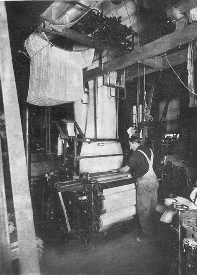
A LOOM PROVIDED WITH A JACQUARD ATTACHMENT
Note the belt of cards that determine the pattern that is to be woven
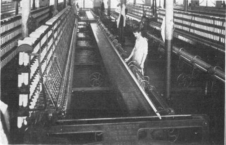
A BATTERY OF MULE-SPINNING FRAMES
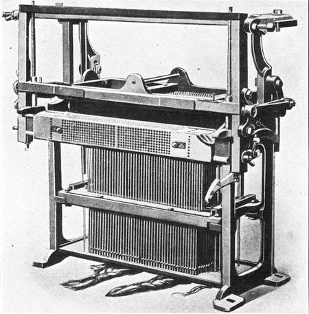
JACQUARD ATTACHMENT FOR LOOMS
SEVEN MILES ABOVE THE EARTH
The greatest altitude ever attained by a balloon has been claimed for Glaisher and Coxwell, who in 1862 went up to a height of seven miles. Both men were overcome by the extreme rarity of the atmosphere. Coxwell, however, although nearly paralyzed and unable to move his arms, succeeded in seizing the safety valve rope in his teeth and pulled it before he lost consciousness. The balloon was then at an altitude of 29,000 feet and rising at the rate of 1,000 feet per minute. Thirteen minutes elapsed before he regained his senses, and then the balloon was falling at the rate of 2,000 feet per minute. From the data furnished, it has been estimated that an altitude of 37,000 feet was reached. While there has been much dispute as to the authenticity of this record, the altitude of 35,100 feet established in 1901 by Professor Berson and Dr. Suring in the German balloon Preussen, probably represents a higher ascent than that of Glaisher’s balloon.
The new system of aerial transportation proved very useful in the nineteenth century. During the siege of Paris, in 1870-1871, sixty-six balloons arose out of the beleaguered city, and all but seven made their escape in safety. In our own Civil War captive balloons were first used to direct the fire of artillery. It was in one of these balloons that Friedrich von Zeppelin, who was a German military attaché with the Union forces, made his first aerial ascent. He was so impressed with the advantages of military observation from such a lofty aerie that he became from that moment an aeronautical enthusiast, and on his return to Germany urged upon the military authorities the importance[226] of the balloon in war. It was then that he began his aeronautic studies and experiments which culminated in the construction of the gigantic ships of the air with which Germany undertook to carry the terror of war into England.
KITE BALLOONS
In the World War captive balloons were extensively used by both sides, an important development being the kite balloon. The common spherical captive balloon is very unsteady except in perfectly still air. It bobs around and swings and turns, making an unfavorable base for careful observation. In heavy winds it is liable to be dashed to earth by sudden gusts. The kite balloon is held up not only by its own buoyancy, but also by the wind in the same way that a kite is supported. The bag is elongated (sausage-shaped) and is fastened to the anchor line in such a way that it is tilted like a kite. To assist in holding it in this position the balloon is ballasted at the after end and the ballast, if you please, is air. A big air-filled bag hangs from the stern of the balloon and serves as a rudder while two other horizontal bags serve as stabilizing fins.
SELF-PROPELLED BALLOONS
No sooner had the Montgolfier brothers proved that it was possible to rise off the earth upon a bubble of hot air, than inventors began to devise schemes of propelling the bubble and controlling its course. The first dirigible balloon was built in 1784 and, strangely enough, oars were used to propel it. The balloon had a fish-shaped body, just like that of modern airships, and the bag was kept[227] inflated by means of air as it is to-day. It was realized even at that early date that the envelope must retain its shape if it is to plow through the air with a minimum of friction. As the gas would gradually leak out of the envelope the bag would become flabby and present a crumpled bow to the ocean of the air and, to overcome this, a double envelope was provided and air was introduced between the inner and outer skin. Means were provided for pumping air in as the gas slowly escaped, thus keeping the envelope fully inflated. As the air was pumped in sand ballast was thrown overboard so that the buoyancy of the airship was not impaired. To-day air is used to keep gas envelopes inflated, but instead of placing the air in an outside envelope it is introduced into a small bag inside called a “ballonet.”
From time to time other means of propulsion were proposed and tried. In 1852 Henri Giffard, who is known as the Fulton of aerial navigation, built and operated a dirigible driven by a steam engine, which he hung at a considerable distance below the gas bag, so that the fire box would not be liable to ignite the highly inflammable gas. A draft was maintained in the fire box as it is in a locomotive by letting the steam discharge into the smoke stack, but in this case the stack was inverted and the smoke and gases were blown downward and away from the coal gas with which the balloon was inflated. The danger of fire and the difficulty of building a power plant light enough to be carried aloft and powerful enough to give the craft any material headway were the chief obstacles that had to be overcome. At the close of the nineteenth century, Santos Dumont, a Brazilian inventor,[228] built a balloon that was driven by a gasoline engine. Despite the apprehension of other aeronauts this machine proved an unqualified success. Two years later, in 1900, Count Zeppelin introduced the rigid dirigible, which to-day is the standard for large airships.
THREE TYPES OF DIRIGIBLES
There are three types of dirigible airships; the flexible, the semirigid, and the rigid. In the flexible type, as we have observed, the envelope must be kept tightly filled in order to hold its shape when driven against the air. The car is suspended from the gas bag. In the semirigid type a rigid frame or backbone serves as a keel for the gasbag and helps to prevent it from crumpling up. In the rigid type a casing incloses the gas or rather bags; for the gas Is contained in a number of separate bags fitted into separate compartments. The casing is composed of a framework of duralumin, which is an alloy of aluminum, with a percentage of copper and nickel. It weighs but little more than aluminum, but is five times as strong. Over the duralumin framework is stretched a sheathing of rubberized fabric. Because of the weight of this casing rigid dirigibles must be made in large size.
ACROSS THE ATLANTIC IN A DIRIGIBLE
Before the war large Zeppelins were built that were fitted with luxurious cabins and dining rooms and made regular scheduled voyages. The big British dirigibles are of the Zeppelin type. The R-34, was 672 feet long and 79 feet in diameter. It was fitted with nineteen gas bags and had a total capacity[229] of over two million cubic feet of hydrogen. It was driven by five engines, each developing from 250 to 275 horsepower, and was capable of making from 50 to 75 miles per hour, depending upon whether or not the engines were pushed. The big dirigible left the Royal Naval Air Station, near Edinburgh, on the 2d of July, 1919, and landed at the Roosevelt Field near Mineola on the 6th, having made the trip in four days and two hours. The course covered about 3,100 sea miles, but the actual air mileage was about 6,300 miles because head winds were encountered. In aeronautic voyages it is the distance through the air that must be reckoned rather than the distance over the ground or sea. An airship may be traveling at the rate of 50 miles per hour through the air, but if there is a wind of 30 miles per hour blowing against the course of the dirigible, the latter will be making only 20 miles per hour over the ground, or if the wind is blowing with the airship it will be making 80 miles per hour over the ground. Because of the head winds the transatlantic flight of the R-34 was so much longer than had been anticipated that its stores of fuel were almost completely exhausted. And yet, when the airship started out from Edinburgh, it carried 81 tanks of gasoline, each containing nearly 70 gallons, or a total of 4,900 gallons. This fuel weighed nearly 16 tons. Almost a ton of oil and 3 tons of water added to the load and the baggage and crew amounted to 4 tons more. The total weight carried was over 24 tons and the dirigible fully loaded weighed altogether about 60 tons. When the dirigible started out it had to fly low, but as the fuel was consumed it grew lighter and rose higher. The surplus hydrogen had to be pumped[230] into steel tanks where, owing to its compression, it was heavy and served as ballast which could at any time be fed back into the gas bags to increase the buoyancy of the airship. We can no longer think of air as having no weight when we consider that all this tonnage was supported by air.
The R-34 was by no means the largest dirigible built, but we dare not boast of the size of the airships of to-day when the aeronautics is in its in-fancy, because our present dirigibles may seem puny alongside the big aircraft that may be built to-morrow. The dimensions of the R-34 have been given because of the historic interest in this first dirigible to span the Atlantic Ocean.
HEAVIER-THAN-AIR MACHINES
Marvelous as was the achievement of the Montgolfiers and wonderful as were the aeronautic developments that followed the invention of the balloon, the dominion of the birds was not really conquered until man had learned how to fly in a machine heavier than the air. Captive aeroplanes date back to the remote ages of ancient history. Kites are really “heavier-than-air machines.” They maintain themselves in the air because they travel through the air at a considerable velocity. True, a kite may be stationary, or practically so with respect to the ground, but if we detach ourselves from the ground and view the situation from a drifting balloon, the earth will appear to be moving under us and the kite will rush past us as it is dragged by the earth to which it is tied. The idea of propelling a kite through the air, not by tying it to the earth, but by furnishing it with its own propeller and power plant, was conceived long[231] ago, but the problem was to find a power plant light enough. The honor of being the first man to rise off the ground in an aeroplane belongs to C. Ader, who made several short flights between 1890 and 1896 in a machine driven by a twenty-horsepower steam engine. Our own S. P. Langley did some most important pioneer work in flying and built a man-lifting, steam-driven machine in 1903 which would have flown had it not been for an accident to its launching gear. In fact, this very model was flown successfully a number of years later. However, it was not until the gasoline engine was developed that the power plant problem was solved. The internal-combustion motor was made more and more powerful in proportion to its weight until now there are several types that weigh less than two pounds per horsepower.
But the power plant was only one obstacle to be overcome. The real problem was to learn how to control the machine after it rose into the air. Otto Lilienthal attempted to learn how to fly in a motorless flying machine. He provided himself with wings and, jumping off a height or running down a slope, depended upon gravity to furnish him with the necessary propulsion through the air. Unfortunately after five years of gliding experiments a fatal accident terminated his aeronautic research.
THE WRIGHT BROTHERS
In this country the Wright brothers, Orville and Wilbur, took up the work of Lilienthal and they, too, undertook to learn to fly before they built a flying machine. In all his years of experiment, Lilienthal did not have more than five hours of experience in the air. The Wright brothers determined[232] to spend more time in the air and less in theoretical speculations at home, so they built a gliding machine that would sustain a man at a speed of eighteen miles per hour and picked out a spot on the Atlantic coast where they were assured of fairly constant winds of sixteen to twenty-five miles per hour. At first the machine was used as a kite and various experiments were made in balancing it. Then short gliding flights were made from the tops of the sand dunes. Not until the art of balancing the glider and controlling it in unsteady air currents was any attempt made at building a motor-driven flying machine. It was by these experiments that the Wright brothers discovered the system of warping the wings so as to preserve the lateral balance of the machine. After several seasons of experimental gliding, and not until they felt that they had learned how to fly, was a power machine built. This made its first flight on December 17, 1903. The first flight lasted only twelve seconds, while the fourth flight lasted fifty-nine seconds. Many months were spent in perfecting the machine and in solving the various problems of flight, and not until September, 1905, did the Wright brothers feel that they had mastered the art of flying. After that three years elapsed before the world was actually convinced of the reality of airplane flight and recognized the work of the pioneers.
TRANSATLANTIC AEROPLANE FLIGHTS
The development of the heavier-than-air machine is so recent and is still advancing so rapidly that we dare not give more than a brief outline of its progress here. The more important advances are familiar to most of us and a record of achievements[233] to-day will be hopelessly out of date to-morrow. The war gave a tremendous impetus to flying. Pilots were trained by the thousand. Machines grew in speed up to 150 miles per hour. Huge bombing machines were built, with a wing spread of over 125 feet, and weighing ten to fifteen tons. These were capable of carrying a load of four to five tons. The first flight across the Atlantic was made in June, 1919, by the United States navy flying boat NC-4, which flew to Newfoundland, then to the Azores, and from there to Lisbon, Portugal. The trip was finally completed by a flight to Plymouth, England.
The first nonstop flight was made in the same month by a Vickers Vimy bomber which, with a favoring wind of thirty miles per hour, made the trip in less than eighteen hours at a rate of 120 miles per hour. To-day all-metal aeroplanes are being flown successfully. Plans are under way to build aeroplanes for service at extremely high altitudes, where greater speeds are possible owing to the tenuity of the air and the consequent lowering of head resistance. These machines are to have inclosed bodies in which air at normal pressure will be maintained by means of blowers. The blowers would also furnish the engines with air necessary for proper combustion of the fuel.
We are not going to give a history of the progress of aviation since the invention of the Wright biplane, but instead we shall look briefly and in a very elementary way into the principles underlying the flight of heavier-than-air machines.
WHY A KITE STAYS UP
What is it that makes a plane or a kite stay in the air? The answer is inertia. The balloon shows us that[234] air possesses weight; the aeroplane shows us that air possesses inertia. This is a natural consequence. Every body possesses inertia and the heavier the body the greater its inertia. By inertia we mean resistance to change of motion or rest. The pressure of air against the face of a fan is due to its resistance to a change from state of rest to a state of motion, while the pressure of wind against a surface represents the resistance of air in motion to being brought to a state of rest. The more sudden the change the higher is the resistance or pressure developed. If an open newspaper be laid over one half of a ruler, while the other half extends beyond the edge of the table, the ruler may be broken by a sharp blow on the overhanging end, not because the other end is held down by the weight of the newspaper, but because the inertia of the air bearing on the broad area of the paper prevents the ruler under the paper from rising in response to the sudden blow at the overhanging end. It is the inertia of the air, i. e., its resistance to rapid displacement that keeps a parachute from falling like a solid shot to earth.
Figure 62 shows how a kite is maintained in the air. The line AB represents the plane of the kite, the line CO at right angles to this plane is the pressure against the center of the kite surface. The wind pressure DO is resisted by the pull of the kite string and exerts a lift EO, which resists the vertical pull of gravity. The sum of the forces DO and EO must be equal to the force CO. If EO is greater than the force of gravity the kite will rise, and if it is less the kite will fall. The magnitude of the force EO depends upon the velocity of the wind DO and the angle of the kite AB to the wind. If the plane of the kite were parallel to the[235] direction of the wind the angle would be zero and the lift would also be zero.
FORCES THAT SUPPORT AN AEROPLANE
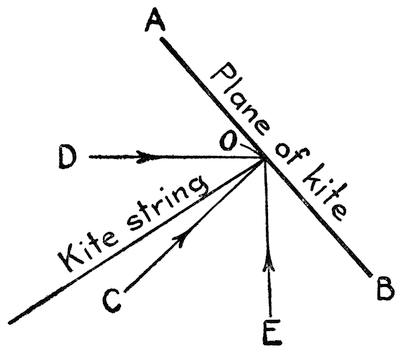
FIG. 62.—FORCES WHICH HOLD UP A KITE
In an aeroplane conditions are just the same as in a kite, except that a propeller drives the plane through the air with a force equal to CO. The plane is slightly curved, so that air which is deflected or forced down at the forward edge will continue to press against the plane all the way to the rear edge. The shape of the top of the plane is also important. As the plane is driven through the air a partial vacuum is formed above the plane, so that the difference in pressure between the two sides is increased and there is a greater lifting effect. This partial vacuum is known as “cavitation.” In the early days of the aeroplane it was not realized how important was the effect of cavitation on rapidly moving objects. Every spar and member of the[236] airplane as it plows through the air builds up a head resistance in front and is followed by a wake of rarefied air unless it is given a stream-line construction. This is illustrated in Figure 63, which shows at the left a rectangular body traveling through the air and at the right a stream-lined body. The flow of the air is indicated by the lines and it is evident that head resistance and cavitation are reduced by forming the body with a bulging bow and tapering stern. To-day all the exposed parts of aeroplanes are stream-lined as far as possible. In the early Wright machines wire braces were extensively used. It was not supposed that a wire would offer much resistance to the air, but, upon investigation, it was found that the wire braces would vibrate laterally and present virtually a broad surface which materially increased the head resistance.

FIG. 63.—FLOW OF AIR AROUND A RECTANGULAR BODY AND A STREAM-LINED BODY
The angle of the plane determines to a large extent the head resistance of the plane. If the plane is horizontal the head resistance is at a minimum, but the lift is also very slight. If the wing planes were perfectly flat, there would be no lift at all, but because of the curve of the wings there is a certain amount of lift when they are horizontal, and even when they are tipped slightly downward, provided[237] the machine is traveling at high speed. The angle of an aeroplane’s wings is therefore much flatter than that of a kite.
MAINTAINING THE EQUILIBRIUM OF AN AEROPLANE
In order to maintain itself in equilibrium the center of gravity must coincide with the center of pressure, otherwise there will be a turning action about the center of gravity and the machine will upset. The location of the center of pressure depends upon the angle of the plane. The greater the angle the farther it is from the forward edge of the plane and the pilot can maintain fore-and-aft equilibrium by tilting the horizontal planes of his rudder so as to change the angle of the machine, and hence of the main or forward planes. Unfortunately the air is a turbulent ocean filled with invisible air currents and the aeroplane must be capable of adjustment to meet the variations of pressure due to sudden gusts of wind. This is particularly true of lateral balance. A gust coming from the side will put a greater pressure on one side of the aeroplane than on the other. To meet this the angle of the plane at one side must be less than that at the other. This was discovered by the Wright brothers and their method of overcoming the lateral variations of pressure was the key to their early success. They warped their wings or twisted them so that the angle of the wing was reduced on the side from which the gust came and was increased on the other, and thus the center of pressure over the whole wing was kept on the line of the center of gravity. At the same time there was a variation in head resistance which had to be[238] corrected by moving the rudder, and the Wright brothers used a single lever to warp the wings and at the same time to operate the rudder so as to keep the aeroplane on its course.
Before the Wright brothers made public their invention other aeronauts had great difficulty in making turns. When turning, one side naturally has to move through the air faster than the other. This produces an increase of pressure on one side over the other which may be counterbalanced by warping the wings. The same effect is produced by the use of small wing planes, called “ailerons,” at each side of the main planes. An automatic means of stabilizing an aeroplane has also been devised, a description of which will be found in Chapter XXI.
CHAPTER XV
HELPING THE FARMER
THE FIRST efforts at directing the forces of nature and employing them in the service of man were made by the farmer. The task of growing food was quite the most important of primitive occupations, and although the virgin soil was rich and the yield abundant there were regions where crops could not be raised except at the expense of constant toil. Infrequent rains made it necessary to carry water by hand from wells and rivers and pour it over thirsty lands. As the grain fields grew more extensive, irrigating ditches were used which saved the toil of carrying the water, although it still had to be raised by hand. Then machines were invented by which water could be raised by animal power and, finally, as we have already seen, automatic water-lifting machines were constructed by which the river itself was constrained to lift a part of itself and pour this part into the irrigation ditches.
While it is true that the earliest machines were built to lighten the work of the farmer, the attention of inventors was soon attracted to other fields of endeavor and the farmer was left to toil slavishly from daybreak to sundown with no further mechanical aid. The tools he used were improved in form and quality. Oxen were used to draw the plow. The wooden plow made out of a forked stick[240] gave way to a bronze plow and, finally, to one of iron. The curved knife or sickle went through a similar process of evolution from flint to iron. It was the only implement used for cutting the standing grain, and not until comparatively recent times did it give way to the scythe. Practically all the work of tilling, seeding, cultivating, harvesting and threshing was done by hand in practically the same way and with practically the same tools from the time of the Pharaohs down to the end of the eighteenth century.
THE FIRST HARVESTING MACHINE
To be sure, there is a record of a harvesting machine built in Gaul, while that province was under Roman dominion. Pliny described this machine in 70 A. D. It consisted of an ox cart which was pushed through a field of grain, instead of being pulled by the ox. This cart carried a rack or comb which caught the heads of the standing grain, tearing them off and delivering them into the body of the cart. Unfortunately this primitive, but useful, harvester was not extensively employed and in time it was lost to agriculture. Farmers reverted to the time-honored method of reaping by hand and the ox-pushed machine was forgotten. From time to time in recent years this machine has been reinvented and a machine similar in principle is used to-day to gather clover seed.
The scythe was a distinct improvement over the sickle. It enabled a man to use two hands at the work of reaping instead of one. It provided a much longer and heavier blade, and hence a much broader swath was cut at each stroke. A distinctly American improvement on the scythe is the grain cradle, consisting of a set of fingers above the blade[241] which catch the grain and lay it in a swath at the end of the stroke. This important improvement rapidly spread to all parts of the world and is still used to-day where it is impracticable to use a mechanical reaper. It is claimed that one man can cut and bind more grain with the cradle than three men could with the sickle.
EVOLUTION OF THE PLOW
The plow has undergone important developments in comparatively recent years. Wooden plows were still in use in America in Revolutionary times; usually the point was shod with wrought iron. However, these wooden plows speedily gave way to metal when iron came to be manufactured in considerable quantity in this country. A plow has to contend with two conditions of service that apparently conflict with each other. The constant friction of the soil against the blade tends to wear it away very rapidly, hence a very hard surface is requisite. On the other hand, the plow is apt to encounter buried stones and rocks which will shatter it unless it is soft. The problem then is to make the plow both hard and soft. The chilled iron plow was invented by Oliver, in 1855, to meet the first condition. When molten iron is poured into an iron mold the surface that comes into contact with the mold is suddenly chilled, producing a very hard surface that takes a good polish. This effect is accentuated by using a hollow mold through which water is circulated. The hard surface of the chilled iron wears well in sandy and gravelly soil, it does not rust deeply, and it clears well in sticky soil. However, it is very brittle and is liable to break if struck a sharp blow. A more recent improvement[242] is the soft-center steel plow. This is both hard and soft. It is composed of three layers of metal; the outer layers are of hard cast steel and the center one of soft steel. These metal layers are heated to a welding heat and then rolled together, producing a plow that has a hard outer wearing surface and at the same time is tough because the center layer of soft steel acts as a cushion to absorb sharp blows. To increase the wearing qualities of the plow still further a patch of very hard cast steel is welded over the point of the share. Thus both conflicting requirements of softness and extreme hardness are met.
We think of the plow as a very simple tool, but the modern implement is a product resulting from a vast amount of study and research into the materials most suitable for its construction and into the best form of share and moldboard. In place of a single plow for all purposes the modern farmer is offered a large assortment to suit various classes of work. At least three different kinds of plows are indispensable on every farm; the sod plow, the stubble plow, and the corn-cultivating plow. The sod plow is used for turning over the sod and breaking the clod. This is provided with a jointer or diminutive plow point set above the share, which turns over the edge of the furrow to prevent grass from growing up between the furrows. The stubble plow has a moldboard with less twist than that of the sod plow. This is used for plowing land that was under cultivation during the previous year.
The plow of to-day has become more than a hand-guided, horse-drawn tool. It has developed into a real machine, mounted on wheels, with a disk or coulter wheel that cuts the furrow cleanly, means[243] for leveling the plow and regulating the depth of the plow, and a seat for the plowman. It works upon soil with the same precision that a planer works upon a slab of cast iron. The furrow is neatly sliced, lifted, and turned over with mechanical accuracy. As the furrow slice slides over the moldboard of the plow the soil is pulverized by friction. The front furrow wheel runs in the furrow previously cut which serves as a track to guide the machine. The front and rear furrow wheels are inclined from the vertical so as to balance the thrust of the plow and they may be given a lead toward or from the “land” or unplowed part of the ground to regulate the steering automatically. The proper adjustment and balancing of a plow calls for considerable skill.
Agricultural operations are now conducted on such a vast scale that the single plow cannot begin to do the necessary work. Instead, sets of gang plows are used so that from a dozen to two dozen furrows may be turned at a time. Steam or gasoline tractors of the wheel or track-laying type are required to furnish the tractive effort needed to haul these huge plows. The larger tractors are so powerful that they haul not only the plow but a harrow behind the plow to break up the clods and a seeder behind the harrow to sow and cover the seed so that all three operations are performed simultaneously.
The disk type of plow is used in very dry and hard soil and also in very sticky soil. A rolling disk takes the place of the moldboard and share, and in this way friction is reduced very materially, with the result that less tractive effort is required to draw the machine.
There is scarcely any agricultural operation for which a machine has not been designed. We cannot attempt to describe them all. For tilling the soil there are plows, harrows, drags, and rollers of many different varieties; for seeding and planting there are grain and seed drills, corn planters, potato planters, etc.; for cultivating or working the growing crops there are cultivators, weeders, fertilizer drills, corn plows, etc.; and for harvesting or gathering the crops there are mowers, hay rakes and tedders, reapers and binders, potato diggers, corn binders and huskers, corn shellers, etc.
INVENTION OF THE REAPER
Most interesting of all are the reapers because they represent the first successful efforts to introduce machinery into farming operations. Toward the close of the eighteenth century the Royal Agricultural Society of England offered a prize for the invention of a successful reaper, which stimulated inventive effort in this field. But although many patents on reaping machines were granted by the British patent office, nothing was produced that completely met the requirements. In fact even as late as 1851 when a World’s Fair was held in London the British had no really successful reaper to exhibit. In the meantime, American inventors had been at work and two inventors in particular, Obed Hussey of Maryland and Cyrus McCormick of Virginia, had developed machines which had so far proved their worth that they were extensively used on American farms. These two inventors, working independently, produced machines that were very similar in basic principles. As our patent regulations of that period did not call for an extensive[245] search of the prior art there was no official investigation to show which was entitled to the honor of priority of basic principles or whether both did not include in their applications much that was old. Hussey filed his patent on the last day of 1833 and McCormick in June of 1834.
The main stumblingblocks of earlier inventors of reaping and mowing machines was in finding a suitable method of cutting the grain. Revolving combs for tearing off the heads of grain, fingers for gathering the grain and holding it against a revolving cutter, horizontally reciprocating knives—all these methods were tried without success. Nearly three years before Hussey obtained his patent, Manning, of Plainfield, New Jersey, solved the problem by inventing a reciprocating cutter with spear-shaped blades cooperating with a finger bar that guided and held the grain against the blades. This invention was apparently unknown to either Hussey or McCormick and their patents show cutting means that were broadly the same as that of Manning.
THE “FULTON” OF AGRICULTURAL MACHINERY
Of the two rivals, McCormick showed the better business ability in perfecting his invention and promoting it so that he eventually became to be considered the “Fulton” of agricultural machinery and the public forgot the pioneer work of Hussey. As a matter of fact, McCormick built his first successful reaper three years before he obtained his patent. Four horses were hitched to the machine and he went out into a neighboring field of oats to demonstrate it. In less than half a day he had reaped six acres, which was a remarkable performance[246] when we consider that a single acre was considered a day’s work for one man. McCormick’s machine had a reel above the cutter to hold the grain against the knife and as the grain was cut it dropped upon a platform. A man walked alongside the machine and removed the grain with a rake. And so the reaper with two men to operate it did the work that had formerly required twelve men with the cradle.
The next important improvement was to provide a seat at one side of the reaper so that the man with the rake could ride. While this reduced the labor of the man it did not materially increase the efficiency of the machine. The next step, however, was of material importance. In place of raking off the hay by hand an automatic rake was furnished and the services of the extra man were dispensed with. One man could then do the work of twelve. McCormick had had difficulty in introducing his machine into public use, but now its superiority over hand labor was so marked that reapers came to be extensively employed on American farms. The reaper had reached this stage of its development when the World’s Fair of 1851 was held in London and McCormick’s machine was sent across the Atlantic to be displayed at the exhibition. At the same time Hussey sent over one of his machines which had reached the same stage of development. There was a British machine also on exhibition based on the invention of Rev. Patrick Bell of Scotland in 1826, but in a competition with the American machines it could not begin to compare in efficiency. The work of the American machines was a revelation to the British farmers. The prize was carried off by McCormick’s machine, which was declared by the judges[247] to be worth the whole cost of the exposition. Unfortunately Hussey was not on hand to direct the operation of his machine, which may have had something to do with its failure, for in another test the Hussey reaper was found superior to the McCormick.
The excellence of American reapers was now well established and their fame spread throughout Europe. In a competitive test held near Paris in 1855, America won the highest honors by cutting an acre of oats in twenty-two minutes as against sixty-six minutes for a British machine and seventy-two for an Algerian machine. In 1878 McCormick was made a member of the French Academy of Sciences in honor of his achievements.
TYING KNOTS BY MACHINE
After the self-raker was introduced the next important improvement was in the binding of the grain. At first the cut grain was raked into a receptacle which was dumped by the driver of the machine when enough had accumulated to form a bundle and the bundles were bound by men following the machine. As in the evolution of the raker, the next step was to provide a platform for these men on the machine so that they could ride as they bound the grain and finally in 1873 a self-binding attachment was invented which increased the efficiency of the machine manifold. This self-binder, however, called for the use of wire which did not meet with favor as a binding material because of the difficulty of cutting it without a special tool. Efforts were therefore made to introduce twine instead. But twine cannot be fastened by mere twisting; it has to be tied and a mechanical means of tying a knot was far from an easy problem to[248] solve. While it is true that the human body is a machine and every movement of which it is capable may be reproduced by mechanical means, the difficulty is to copy many operations without involving such complexity of members as to make the mechanism wholly impracticable. The human hand is really a very intricate piece of mechanism which by long generations of evolution and development has become wonderfully deft. It exhibits this deftness and complexity of movement in tying knots and the very intricacy of this operation was enough to baffle the majority of inventors. There was one inventor, however, who was not to be thwarted even by so formidable an obstacle as this. In 1864 Jacob Behel secured a patent on an attachment for binders which would actually tie a knot. The mechanism passed the twine around the gavel of grain, formed a loop in the two ends, and tied a simple overhand knot in much the same way that the hand ties this knot. Ten years later Marquis L. Gorham improved the mechanism and built a successful twine binder. Finally in 1879 John F. Appleby perfected the binding mechanism, completing the last stage in the development of the modern automatic self-binding reaper.
To keep pace with the reaper, other agricultural machines had to be invented and developed. The vast quantity of grain harvested could not be threshed by hand and the old-fashioned flail had to give way to the steam-driven threshing machine. Finally to meet the requirements of the vast western wheat fields, the combined harvester and thresher was developed which, with a crew of four men, will reap, thresh, and bag between two and three thousand bushels per day. According to statistics[249] of the U. S. Department of Agriculture it took a man three hours and a half to produce a bushel of wheat in 1830 as against ten minutes in 1896. Surely the world owes a tremendous debt to Hussey and particularly to McCormick for introducing machinery into agriculture and starting the train of inventions which in the space of two-thirds of a century have led up to the present remarkable era of machine farming.
There still remains one task of the farmer that has not yet been accomplished with unqualified success by machine. The harvesting of the corn crop is a tedious and disagreeable task and one which the farmer would only too gladly turn over to the machine. To be sure, many corn-harvesting machines have been built and put into service with more or less success, but none has reached the perfection of other classes of agricultural machinery. The difficulty lies not in the machine, but in the fact that corn is so easily beaten down by storms that at harvest time the machine seldom finds the stalks all standing up in nice straight rows. Machines must therefore be provided with means for lifting up the fallen stalks to vertical position. The stalks are cut and bound into bundles and stood up in shocks.
Even more difficult than cutting and binding is the task of husking the corn. This work was always dreaded by farm hands, but now machines are provided to husk the ears and shred the stalks for fodder. Thus the farm is being relieved of its drudgery. Unfortunately it is only the large western farms that can afford to avail themselves of the latest agricultural machinery. On small eastern farms it does not pay to purchase a machine which can be used for only a few weeks in the year and then must[250] be stored away until the next season, but small farmers are now cooperating and clubbing together to buy the less frequently used machines and so even the small farm is being relieved of its drudgery, and the arduous burdens which have always had a tendency to drive young men away from the farm are now being assumed by the unfeeling machine.
CHAPTER XVI
MACHINING THE EARTH
THE ALBANIAN people have a story that the Creator recently visited the earth and was astonished to find how it had changed. “Why, this is not the earth I created,” He said. “Everything has changed. My forests are cut down; My rivers have been diverted from their courses; My hills have been blasted away, and My mountains have been robbed of their minerals. The whole face of the earth has been altered.” But in the course of His roamings, the Creator suddenly came upon the land of Albania. “Ah!” He exclaimed in delight. “Here is a bit of earth untouched by man. It is still just as I made it.”
Man’s ambition to make over the face of the earth to his own liking dates far back of the present age of machinery. However, the work of the ancient engineer was accomplished only at the expense of decades and generations of hard manual labor. To-day, with powerful and gigantic machinery to do our bidding, we do not hesitate to change the course of rivers, to level off the hills, to carve highways through the mountains and pierce them with tunnels, to bore into their depths for treasure and drive deep holes into the bowels of the earth in quest of liquid fuel. We are able to machine the earth in much the same way as a piece of metal is machined in the machine shop. In fact, the drill,[252] the circular saw, the slotter, and even the milling machine have their counterpart in the excavating machinery of to-day. Of course we cannot expect to find the counterpart of such machines as the lathe, boring mill, and planer, in which the work revolves against the tool, because this planet of ours is rather too big a piece of stock to be placed between lathe centers or to be bolted to a planer bed.
MECHANICAL MONSTERS
The twentieth century finds this planet again stocked with monsters larger and more powerful than the gigantic saurians that dominated the earth in the Jurassic and Cretaceous epochs, but our mighty fire-breathing, steel-sinewed beasts are humbly subservient to the will of man.
The spectacle of a large steam shovel at work makes one feel at once very small and very big. Before the work of this monster the human shoveler shrinks to the proportions of a mere insect. Seven to eight cubic yards shoveled into a cart is considered a fair day’s work for a laborer, but a big steam shovel can easily gobble up as much material in two bites. However, when we contemplate that this mammoth machine is a human creation and an absolute slave to human command, we are rather inclined to be puffed up with the greatness of man.
Steam shovels are ideal machines for excavating railroad cuts and were primarily developed for just such work. The general operation of the machine is very similar to that of hand shoveling. The shovel proper consists of a big scoop or dipper and a dipper handle which correspond respectively to the blade and handle of a hand shovel. Like the[253] shovel, the dipper is supported at two points. The dipper is suspended by a chain from the end of a boom while the handle of the dipper is also supported in the boom. By loosening the hoisting chain the dipper is lowered to the ground, and by moving the handle forward the toothed cutting edge is made to bite into the ground or sand bank. The hoisting chain then hauls up the dipper, making it scoop out the bank, after which it is swung to one side over a car on an adjoining track. The rear of the bucket is fitted with a door which is opened by a spring latch and the contents are emptied out. Some of the largest steam shovels for ordinary grading have dippers with a capacity of 5 cubic yards. They are not confined to railroad grading, but are applicable to any excavation where a firm footing is provided for the heavy machine. They are even used for excavating the cellars of large city buildings. The machine must be supported on road wheels or on skids. When used for excavating sewer trenches, it is sometimes mounted on a platform spanning the trench. However, the steam shovel is rather limited in its reach. The largest ordinary steam shovels have a clear lift of but sixteen feet and can make a cut only sixty feet wide at the top.
For more extensive excavating as well as for digging ditches and trenches the drag-line excavator has recently come in to use. In these machines a scraper takes the place of the dipper. This is suspended from the end of a long crane and it is dragged along the ground by a cable, scooping up a load of earth. In some cases the scoop or scraper is merely attached to a cable leading from the hoisting engine to an anchorage and back to the engine.[254] To adapt excavating machines for service in soft ground they are mounted on broad wheels or on track-laying tractor surfaces. One peculiar form of walking traction used by a drag-line excavator was described in Chapter XIII.
DITCHING AND TRENCHING MACHINES
For digging narrow ditches and trenches, particularly for sewers, water mains, gas-pipe lines, etc., a number of very interesting machines have been invented which are of two general types, the endless chain and the wheel excavators. The first type consists of a traction engine with a ladder at the rear that drops down into the trench. About this ladder runs an endless chain which carries a series of scoops or buckets. These are dragged up against the breast of the work and carry the excavated earth to the top of the ladder where it is dumped upon a transverse belt conveyor and carried to one side of the trench. With the larger sizes of chain excavators, trenches may be dug to a depth of twenty feet and the width of the trench may be from two to six feet wide.
The wheel type of trenching machine is similar in principle to the chain excavator. Instead of the chain of buckets, it has a wheel fitted with buckets. In one prominent type the wheel has no hub or spokes, but consists of a rim that is supported on and is turned by four friction rollers mounted in a rigid frame. This frame is mounted on a boom which can be raised or lowered as desired. Such machines can commonly dig to a depth of a dozen feet or so.
A ditch differs from a trench in the fact that its side walls are sloping instead of vertical. A trench is usually a temporary excavation for the laying of[255] pipes or conduits while the ditch is left open and serves for irrigation or drainage. There are chain ditching machines in which the chain of buckets runs laterally across the course of the ditch, dipping into the earth to form a V-shaped channel. In connection with the draining of the Everglades of Florida, a peculiar wheel type of ditcher was built. The wheel is of gigantic proportions, consisting of a series of radiating shovels or scoops shaped to conform to the outline of the ditch. As the wheel revolves it scoops up the mud which slides down toward the hub of the wheel and is carried to one side by a traveling conveyor.
FLOATING EXCAVATORS
The main difficulty in drainage work is to provide a good footing for the machine which must necessarily be very heavy. Broad caterpillar tread surfaces are about the only means of locomotion. In very soft swampy regions dredges have to be used. Dredges are merely floating excavators. In them the problem of support and locomotion disappear and there are no limitations of size and weight to be considered. Floating excavators are therefore much more powerful than excavators that run on land. The ordinary dipper dredge is merely a floating steam shovel with a much longer dipper handle and much larger dipper. When work on the slides of the Panama Canal had proceeded far enough to admit of using dredges in place of steam shovels material progress was made. Two enormous dipper dredges were built, each provided with a dipper that had a capacity of fifteen cubic yards or about twenty tons at a single lift. The dipper was big enough to hold thirty men. The[256] dipper handle was seventy-two feet long and it could reach down to a depth of fifty feet. A smaller dipper of ten cubic yards capacity was also provided. The power of these huge dredges was illustrated when one of them, while using its ten-yard bucket, picked up an enormous bowlder weighing forty tons. It was much bigger than the dipper that had raised it and it was far too big to be placed on the mud scow that was receiving the spoil brought up by the dredge. Had it been rolled off on the scow it would have crashed right through the bottom of the boat and so the big rock had to be drilled and broken up on the dipper before it could be dumped into the scow.
For work on a soft bottom, grab buckets are used in place of dippers. These may be made of two scoops as in the clam-shell bucket or of four leaves as in the orange-peel bucket. No rigid handle is provided for these scoops. They are spread open as they are lowered into the water and on hauling in the hoisting cable, the scoops or leaves come together biting into the bottom and lifting up a load of mud. Grab buckets are largely used for picking up coal, ore, gravel, etc.
The equivalent of the chain trench-digging machine is found in the ladder dredge. A ladder is hung over the stern of the dredge and carries a chain of buckets which dig into the bottom and bring up the mud or sand.
GOLD MINING WITH A DREDGE
It is a dredge of this type that is put to the peculiar task of gold mining. The dredge eats its way into gold-bearing sands, the material passing through a system of separators which extract the gold and then being discharged at the rear of the dredge. The dredge floats in a pool of water that it carries with it, for as it excavates ahead it builds up sand banks behind. In this way it may travel far from the river from which it first started.
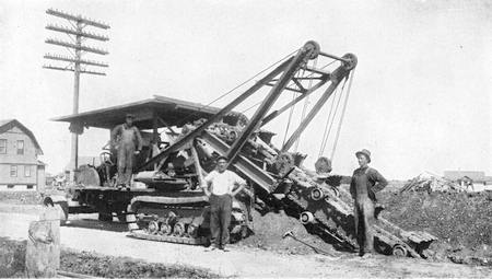
DIGGING A TRENCH WITH A CHAIN TYPE MACHINE
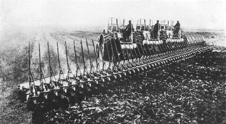
MULTIPLE PLOWING ON A WESTERN WHEAT FIELD—TURNING FIFTY FURROWS AT ONCE
SUCTION DREDGES
Suction dredges are particularly adapted for excavating sandy bottoms. One type used for dredging channels consists of a large steam vessel with large bins into which the dredged material is pumped. At each side of the boat there is a long pipe which may be let down into the water. Each pipe terminates in a drag or footpiece with grated opening which is designed to be dragged along the bottom as the vessel slowly steams ahead. Powerful pumps suck a stream of water up the pipes which carries with it a quantity of sand. The sand and water flow into the bins, the solid matter settling to the bottom while the liquid flows out over the top. When the settlings have filled the tanks, the drags are pulled up and the vessel steams out to sea. Here doors in the bottom of the bins are opened and the material drops through. The idea of opening up the bottom of a boat to empty it seems rather startling until we consider that the bins are sealed off from the rest of the boat and do not contribute to its buoyancy. The sand that is dumped out of them is much heavier than the water that takes its place when the bin doors are opened.
CANAL DIGGING UNDER WATER
The Ambrose channel in lower New York Bay was dredged by means of suction dredges. The channel is forty feet deep at low water and the bottom had to be excavated from ten to twenty-five[258] feet to attain this depth. About seventy million cubic yards of material had to be excavated or nearly a third as much as was excavated in the Panama Canal. The Ambrose channel is seven miles long while the Panama Canal is forty-five miles in length. Two of the larger dredges each had a capacity of forty-five hundred cubic yards in their bins or enough to load a train about a mile long, composed of 175 cars. It took less than three hours to fill the bins. The openings in the gratings of the drags measured about eight by nine inches and any stones or solid matter small enough to pass through them was easily sucked up into the bins. When a pile of stones of larger diameter was encountered a deep hole was dredged around it and then by means of a water jet the stones were forced into the hole.
The material sucked up by a dredge is sometimes dumped into a scow alongside. This makes the structure of the dredge less expensive, but where work has to be conducted in bodies of water exposed to storms it is more expedient to let the dredge collect the material within its own hull.
LAND BUILDING WITH DREDGES
The sand drawn up by a suction dredge is valuable material for land building. In fact, a suction dredge is often used for the double purpose of excavating and filling in low land. Sometimes its only purpose is to fill in tide flats to above tide level. The material is discharged through a pipe line which may be over a mile in length. This pipe line is supported on a string of wooden or steel pontoons. The pipe sections are connected by means of heavy rubber sleeves so as to make the line flexible. This permits the dredge to move about and also allows[259] of moving the discharge end about to distribute the sand properly.
Unfortunately all dredging does not consist of sand and mud. Sometimes snags and matted roots are encountered which give trouble. For handling such material rotary cutters are used. The bow of the dredge is fitted with a hinged ladder about sixty to seventy feet long in which the cutter is mounted. The ladder also carries the suction pipe close to the cutter. The ladder is lowered to the bottom and the revolving cutter chops up the roots into pieces which are drawn up into the suction pipe. The size of the pieces that are sometimes sucked up is remarkable. The greater part of the area of the New Orleans Inner Harbor Navigation Canal was filled with stumps and matted cypress roots. The cutters tore up and cut these roots and stumps and the pieces were transported through a pipe line about 600 feet long. Stumps that were too large to be handled in this way were undercut and sunk below grade.
Cutters are used also for loosening packed hard bottoms and some of them will dig into hard pan and even soft rock. A pressure of 100 to 150 pounds per square inch is maintained in a discharge pipe twenty to twenty-four inches in diameter, which is enough to carry along heavy bowlders dug up by the cutter.
THE DEEPEST MINE SHAFT
So far we have dealt only with surface conditions, but man has not been content to stay on the surface of this planet. True, we have scarcely begun to explore the crust of the earth. The deepest mine in the world is the Morro Velho in the province of Minas Geraes, Brazil. Here the earth has been[260] penetrated to a depth of 6,426 feet in quest of gold. This is a depth of less than a mile and a quarter and it shrinks into insignificance when we reflect that we must go more than 3,000 times that distance to reach the center of the earth. However, we have made material progress in shaft-sinking in recent years, and it is quite likely that the lure of scientific research may prove even more powerful than that of gold and that some day we shall be induced to dig many miles into the crust of the earth just to learn something more about this globe that whirls us through space.
We have not yet reached the point at which hand labor may be dispensed with in tunnel work, but there are machines which will do what formerly could only be accomplished with the manually wielded pick and shovel. We have already (in Chapter VII) described the pneumatic tunnel shield and explained how it is sometimes driven forward through soft silt by means of hydraulic jacks without any excavation of material. This method of tunneling which is analogous to driving a punch through soft metal, has a very limited field of application. It is impossible to force the shield in this manner through sand or through any but very soft silt.
TUNNELING BY MACHINE
The city of Cleveland takes its drinking water from Lake Erie. In order to obtain water that is not contaminated by the refuse of the city, tunnels are carried out under the bottom of the lake about two miles from the shore where they terminate in water intakes far enough below the surface to avoid floating impurities and far enough above the[261] bottom to avoid impurities that have settled to the lake bed. The material through which the tunnels pass is a stiff clay, that cuts like cheese. So uniform is this material that a special machine was built to bore the tunnel through it. This machine is somewhat similar to a boring mill. It has an arm that revolves against the face of the tunnel heading and carries a cutter that travels along the arm so that it cuts a continuous spiral ribbon of clay. The clay ribbon passes back through the machine and is loaded into a train of dump cars.
For boring tunnels in hard rock many different machines have been invented, but not one of them as yet has proved an unqualified success. One very interesting machine, which was tried on the New York subway excavation at 42d Street and Lexington Avenue, consisted of a series of chipping hammers which, by means of pneumatic mechanism, were made to hammer and pulverize the face of the rock with repeated blows. The hammers were arranged in a circle and were revolved as they hammered so that the whole surface of the heading was attacked and a circular tunnel was cut through the rock. A serious disadvantage under which the machine labored was the fact that the rock had to be crushed to a powder or into small chips before it could be removed.
In ordinary rock excavation holes are bored into the heading and the rock is then blown out by means of dynamite or some other explosive. Large fragments of rock are then broken up into pieces small enough to be handled readily, but no energy is wasted in reducing the material to a powder. The percussion drills with which the rock is bored have already been briefly described. When boring holes[262] for a blast in soft material, such as bituminous coal, a drill is used which resembles in many respects an ordinary twisted auger bit except that it is many feet in length. It is driven by hand into the coal by the use of a common bit brace. Percussion drills or punches are also used. These are driven either by pneumatic or electric power.
COAL-CUTTING MACHINERY
When excavating coal the heading is first undercut, that is, a deep slot is cut in the wall of coal along the floor line. Then blast holes are bored into the coal above this cut so that when the charges are fired the coal will be broken downward. To undercut the coal special machines are used, driven by compressed air or electricity. These have endless chains fitted with chisel or pick points that bite into and cut the coal. After the material has been shattered and reduced to fragments of convenient size special machinery may be employed to shovel it away from the heading and into dump cars. One electrically driven shoveling machine which was tried out on some of the Catskill aqueduct excavation had a broad open shovel which could be driven into the pile of rock fragments under the control of an operator and would scoop up the material, delivering it upon a traveling belt conveyor which carried it on to the train cars. Many types of mechanical shoveling and loading machines have been built for use in mines. They are driven either by pneumatic or electric power.
EXPLORING SUBSURFACE CONDITIONS
In all engineering work it is highly important to explore subsurface conditions before starting[263] any construction or even drawing up plans. The ordinary pneumatic percussion drill will not serve for deep holes. Instead a rotary boring motion is requisite. The tool is mounted with black diamond cutters which cut through the hardest rock. Water is introduced into the hole to lubricate the tool and also to wash out the abraded material. By trapping this material the character of the rock penetrated may be determined. The material, however, is pulverized and does not furnish, as a general rule, a fair sample of the rock. When it is highly important to determine the exact nature of the rock or other material a core drill is used. In other words the drill is a hollow tube set with cutting crystals about its periphery. As the tool is revolved it cuts an annular slot in the rock leaving a central core standing. This core is broken off and drawn to the surface and furnishes a true sample of the material encountered by the drill.
There is an interesting type of core drill in which steel shot is used in place of diamonds. The cutting end of the drill is a collar with a notched edge. Steel balls are fed into the drill and under the cutting head. The balls are caught in the notches and rolled around against the rock surface. There is also a partial dragging action. The friction is sufficient to wear away the rock. As the balls wear away they are replaced with new ones. Very evidently such drilling costs less for upkeep than diamond drilling, but it is not as rapid as the latter.
LOCATING ROCK UNDER HUDSON RIVER
A notable illustration of exploration drilling was furnished by the surveys for the Hudson crossing of the Catskill Aqueduct. To bring water from the[264] Catskill Mountains to New York City it was necessary to cross the Hudson River. In order to furnish a permanent conduit it was decided to carry the water in an inverted siphon bored through solid rock. It was necessary to obtain a profile of the rock at the point where a crossing seemed most feasible. Borings were therefore made from a barge anchored in the river, but it was impossible with such an unsteady working base to carry on the boring to any considerable depth. Tides, the wash of passing steamers, floating ice, all combined to obstruct the work. Drills were constantly broken. Finally it was decided to do the boring from opposite banks of the river at such an angle that bore holes would meet or pass each other under the middle of the river. The exploration boring from the barges indicated that solid rock lay at a considerable depth below the river bed and that the bore holes would have to be set at a sharp angle to keep from breaking through rock. The river at that point is about 3,000 feet wide and a boring from the surface at the middle of the river had been driven to a depth of 768 feet without striking solid rock. Two shafts were sunk to a depth of about 250 feet and from these diamond drill borings were started at such an angle that they would cross at a depth of 1,500 feet. Excellent rock was encountered throughout the boring. Then a second set of borings was made which crossed at a depth of 950 feet without encountering any appreciable amount of water. It was accordingly decided to carry the aqueduct in vertical shafts, one at each side of the river, at a depth of 1,100 feet below water level, and then connect these shafts with a horizontal tunnel. It was important to have a good solid rock[265] cover over the tunnel because the aqueduct reaches the river with a head of 400 feet which added to the 1,100 feet of depth of the inverted siphon gave a total head of 1,500 feet or a hydraulic pressure of about forty-two tons per square inch.
Although the diamond drill borings just mentioned were remarkable because of their inclination and because of the cramped quarters from which they were driven, they do not begin to compare in depth with some of the borings made in search of water and of oil. The deepest boring in the world to date is near Fairmount, West Virginia, where a hole six inches in diameter was driven to a depth of 7,579 feet or nearly a mile and a half. At that point an earth slide stopped further borings.
BORING FOR OIL
The time-honored method of boring for oil known as the percussive system is to hammer through the earth and rock with a heavy steel drill. The drill really consists of a long string of parts measuring altogether as much as sixty feet in length. (See Figure 64.) The drill proper or bit has a cutting edge adapted for the character of the material it is to penetrate. The bit is attached to a steel bar known as the “auger stem” which may be from twelve to forty-five feet in length. Then come the “jars” or a link member which allows a play of about sixteen inches. The purpose of this is to assist in freeing the bit from the material it is penetrating by jarring it upward on the upstroke of the drill. Above the jars there is another bar known as the sinker, and this is provided with a rope socket to which is attached the cable that carries the string of drill parts. The cable passes over a pulley to a[266] walking beam which gives the necessary up-and-down motion.
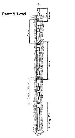
FIG. 64.—A STRING OF WELL-DRILLING TOOLS
The loose material in the bore is removed by a sand pump. To protect the bore from caving a casing of steel pipe must be lowered into the well. The boring may proceed at the rate of ten to sixty feet per day, depending upon the material penetrated and the depth of the well. All sorts of difficulties are liable to interrupt the work. The cable may break, the string of tools may become unscrewed, or the casing may drop into the hole, and[267] then follows the tedious process of fishing for the lost parts and hauling them up out of the well.
As the drilling proceeds, the bore becomes progressively smaller and casings of smaller diameter must be used. The well is completed by lowering a pipe within the casing through which the oil flows to the surface and is carried to the storage tanks and thence by pipe lines to the refineries.
While the percussive system of drilling is very generally used throughout the American oil fields, rotary methods of drilling are largely employed in California.
CHAPTER XVII
FROM FIBER TO FABRIC
IT IS NOT very long since the spinning wheel and the clacking loom were an indispensable furnishing of every farmhouse and of many city dwellings as well. With infinite patience the fleece of sheep, the lint of flax, the filaments of silk and the fibers of cotton were spun into yarn and then woven into cloth, and it was the nimble fingers of the housewife that carried the process through from the matted raw product to the finished garment.
It is comparatively easy to comprehend the development of machines for dealing with such gross material as earth, rock, iron, and wood, but when we come to consider the infinitely delicate and almost imponderable fibers that go to make up our textiles, the marvel is that any but highly skilled human hands, guided by keen eyesight, could combine the tangled and obstreperous filaments into fine yarn and weave this yarn into complicated patterns of cloth. But the spinning wheel and hand loom could not stand long in the path of power-driven machinery, and now huge, blind machines, with stiff, unbending fingers of metal, comb out the matted masses of raw material, remove the dirt and twigs, straighten out the snarls far quicker and better than could be done by hand, and transform the fibers into beautiful fabrics such as in former days would have been the envy of kings.
We cannot attempt to describe all the machinery involved in the spinning and weaving of yarn, but it is highly important that every well-informed person have a general knowledge of textile machinery. Because cotton cloth is more widely used than either linen or wool, we shall confine ourselves to the cotton branch of the textile industry, particularly as the difference between the treatment of cotton and other textile materials lies chiefly in the preparation of the thread or yarn.
The predominance of cotton among textiles may be traced back to the invention of a young New Englander fresh from college, who went to Georgia as a private tutor, only to find when he got there that some one else had been engaged in his stead, leaving him stranded and practically penniless in a strange land. We had occasion to refer to this man in Chapter III. Eli Whitney was a born mechanic, and before entering college had not only shown great skill but had actually built up a thriving business in the manufacture of nails, hatpins and knife blades.
INVENTION OF THE COTTON GIN
The agricultural condition of Georgia and its neighboring States at the time that Whitney arrived there was very poor. There was no market for their products. A splendid cotton, with fibers from 1⅜ to 2½ inches long, was growing on the islands along the coast, but this cotton could not be raised inland. The upland product, known as “green seed” cotton, had a fiber only half as long as the “Sea Island” cotton, but the principal drawback to its use was the difficulty of separating the fiber from the seed. It was a day’s work[270] for one woman to separate a single pound of the “green seed” cotton fiber.
His attention having been brought to this matter, Whitney undertook to design a machine which would remove the fiber from the seed in a small fraction of the time required by hand labor. He was visiting at the time at the plantation of Mrs. Greene, widow of General Nathaniel Greene, of Revolutionary fame, and he set himself to the task with such limited materials and tools as he could find on the estate. In a couple of weeks he had built a model which contained all the essentials of the modern cotton gin, with which a single man could separate more cotton in a day than could be produced by hand in a whole season. This was in the winter of 1792. The effect of the invention was felt immediately. Cotton production had been falling off steadily. In 1791, 189,316 pounds of cotton had been exported. The next year there was a falling off to 138,328 pounds, but following the introduction of the cotton gin exports rose to 487,000 pounds in 1793, 1,681,000 in 1794, and 6,276,000 in 1795. Fifty years later the world production amounted to 1,169,600,000, nearly seven-eighths of which was contributed by the United States, and of this only a small amount was Sea Island cotton.
A cotton gin (Fig. 65) consists of a gang of circular saws (A), with forwardly pointed teeth which pass between the ribs of an inclined grating (B) that forms the floor of a chamber (C) known as a roll box. In this box is mounted a toothed roller (D). The cotton is fed into the box and the fibers are seized by the teeth of the saws and dragged through the grating while the seeds, being too[271] large to pass through, are left behind and, rolling down the grating, drop into a hopper. The action of the saws is such as to impart a rolling motion to the mass of cotton, and hence to the roller in the roll box. This tends to drag the cotton into the roll box and bring fresh supplies to the saws. The fleece carried by the saw teeth is beaten off by a wheel (E) fitted with wire brushes. These brushes, traveling in the same direction as the saw teeth, but at a higher velocity, readily disengage the fibers from the teeth and create an air blast that blows the cotton fleece out of the gin.
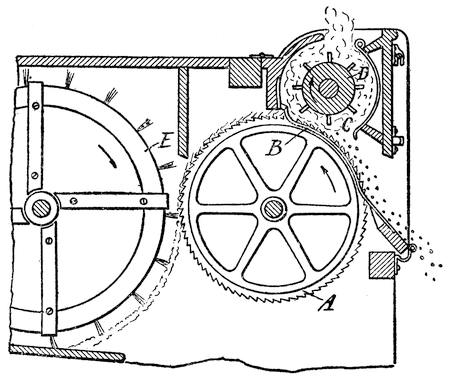
FIG. 65—SECTIONAL VIEW OF A COTTON GIN
PREPARING COTTON FOR THE SPINNING MULE
Cotton as it comes from the bale is a compact, matted mass, mixed with bits of seed, leaves, sand, and other impurities, and it must pass through a[272] number of machines before it comes out as a pure, light, fleecy product, with the fibers combed parallel. Even for a medium yarn a dozen machines are required to prepare the cotton for the spinning mule.
A system of “counts” is used to indicate the size of yarn and it is based on the number of hanks it takes to make a pound. A hank is always 840 yards and 50’s would mean that the yarn is of such fineness that it would take 50 × 840 yards (=4,200 yards) of it to weigh a pound. Yarn below 30’s is graded as coarse; between 30’s and 60’s as medium and above 60’s as fine. To prepare cotton as it comes from the bale for a fine yarn of, say, 100’s, it must go through no less than sixteen machines before it reaches the mule.
We have not the space to describe all of these machines, but in general it will suffice to say that the cotton is graded by passing it through a series of pickers. These machines throw out the fibers and beat them so as to knock out the impurities and, at the same time, a blast of air blows out the dust. The cotton is treated by a number of such machines in succession and is finally delivered in a broad sheet known as a “lap,” after which it passes through the carding machine which combs out the tangled bunches and removes further impurities from the lap. The lap is then gathered into a compact rope known as a “sliver.” The sliver goes through the drawing rolls which serve to parallelize the fibers and make the sliver of even thickness, and at the same time to give a moderate amount of twist so that it will hold together, and it issues from the machine as “roving.” In the case of fine yarn the sliver issuing from the carding[273] machine goes through a combing machine so as to remove the finer fibers. The bobbins of the roving are then placed in the spinning machine, which may be either the spinning mule or the ring spinning machine. The principal difference between the two is that the spinning mule is intermittent in its operation, while the ring spinner not only spins the roving into yarn but at the same time winds it up on a bobbin.
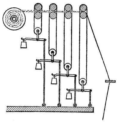
FIG. 66.—ARKWRIGHT’S DRAWING ROLLS
ARKWRIGHT’S DRAWING ROLLS
The first advance over the old-fashioned spinning wheel, which dates back to the fifteenth century, was in 1770, when the first spinning jenny was invented by Hargreaves. This consisted practically of a multiple spinning wheel by which one man could spin a large numbers of bobbins of yarn at the same time. It was at about the same time that[274] Arkwright invented the drawing rolls which have played a most important part in the preparation of yarn, and this invention is worthy of our attention because it contains an interesting mechanical principle. As shown in Figure 66, a number of pairs of rolls are provided through which the roving passes, but successive pairs operate at higher velocities. Thus, the second pair of rollers through which the roving passes run at a little higher speed than the first pair, the third a little higher than the second pair, and so on. As a result, the roving is drawn out by the operation and issues from the last pair of rollers at a higher speed than it entered the first pair of rollers. The only way in which it can accommodate itself to this accelerated motion is to be attenuated or drawn out. Weights are used, as shown in the drawing, to press the upper rollers against the lower ones.
THE SPINNING MULE
Shortly after Arkwright’s invention came the mule spinner, invented by Crompton between 1774 and 1779. Machines operated on the same general principle as this are in general use to-day. In the old-fashioned method of spinning by hand the worker took a small quantity of cotton, pulled it out into a long sliver, attached one end to a bobbin and gave the bobbin a twirl between his hands in order to spin the fiber into yarn; then the yarn was wound up on the bobbin and the process was repeated. The spinning mule does practically the same thing, but infinitely faster and on a much larger scale. As shown in Figure 67, the bobbins of roving (A) are mounted on a stand and passed through a set of drawing rolls (B) which are regulated to pull the rovings out to the desired thickness of yarn. The roving then passes to the nose of a “cop,” or spindle (C), which is revolved at very high speed. The cop is carried by a carriage (D) which moves away from the bobbins of roving to the position indicated by dotted lines, while the cop is revolving. The cop has a travel of about five feet during the time the yarn is drawn out and spun. Then the carriage moves back toward the stand upon which the bobbins of roving are mounted and the spun yarn is wound up on the cop. The reason the yarn does not wind up on the cop while it is spinning is because it runs to the nose of the cop and, at each turn of the cop, the coil twists on the nose and slips off. On the return of the carriage, however, a set of wires (E), called “fallers,” press the yarn down so that the revolving cop will wind up the slack.
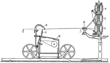
FIG. 67.—DETAILS OF A SPINNING MULE
The continuously operating ring-spinning machine is provided with a ring frame (Figure 68) around the cop or spindle. This frame, together with the spindle, revolves at high speed, but as the ring revolves a little more slowly than the spindle it winds the yarn comparatively slowly upon the spindle or bobbin.
WOVEN, BRAIDED, KNITTED, AND NET GOODS
Having now produced our yarn, we may pause to consider the different types of fabric into which it may be formed, and to draw a distinction between, woven, braided, knitted, and net goods. In weaving we have two sets of threads, one set running transversely to the other; in braided materials the threads all run longitudinally and are arranged to cross each other diagonally, so that they are interwoven;[277] in knitting and netting there is a single thread. In the case of netting this thread is knotted where it loops back upon itself, whereas in knitting it is merely looped without knotting.
THE LOOM
The loom can trace its genealogy away back to early Babylonian times, and the modern power-driven machine does not differ in its broad principles of operation from its ancient progenitor—the hand loom.
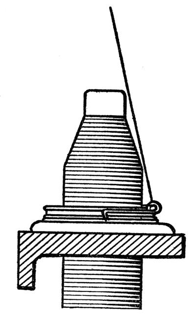
FIG. 68.—RING-SPINNING FRAME
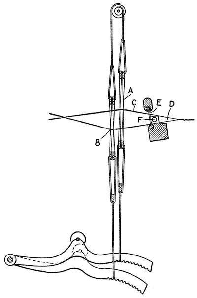
FIG. 69.—THE HEDDLES OF A LOOM
Every industry has a vocabulary of its own to furnish names for its machine parts and products peculiar unto itself, and in this respect the textile industry is by no means an exception. The threads that run lengthwise in a piece of woven cloth are known as the “weft,” “woof” or “filling.” In the loom the warp threads are threaded through loops on what are known as “heddles”; in fact, there are two “heddles,” A and B, Figure 69. Alternate warp threads (C) pass through the loops of one heddle, and the other threads through the loops[279] on the other heddle. When one heddle is raised and the other lowered, the threads form a wedge-shaped space (D) which is known as a “shed.” The filling thread is sent through the shed and is then pressed closely into the wedge-shaped space against the cloth already woven by means of a “reed” (E) which is a comblike member with teeth or flat pieces of metal that pass between the warp threads. This done, the position of the heddles is reversed, so that A is now lowered and B raised, thus binding the warp thread in place and forming another shed for the next warp thread; and thus the process continues.
The filling thread is placed in a shuttle (F) which carries a bobbin on which the thread is wound. As the shuttle is thrown back and forth through the shed, the thread is unwound and trails behind it. Formerly the shuttle was thrown back and forth by hand, but years ago, long before the invention of the steam engine, the flying shuttle was invented. In other words, a mechanism was provided for striking the shuttle a blow and throwing it across the warp from side to side. By this means the speed of operations was greatly increased.
About the middle of the eighteenth century the drop box was invented. This consists of a receptacle for shuttles carrying different colors of thread which may be selected in a definite order and thrown back and forth so as to vary the pattern of the cloth.
In present looms a special machine is provided for taking the threads from the bobbins or cops and laying them in an even sheet to form the warp of the loom. These are wound on a beam and the[280] machine is known as a beam warper. As the threads are apt to be somewhat fuzzy it is necessary to size them, and a machine known as a slasher is employed for this purpose. This machine coats each thread of warp yarn with a sizing compound or an adhesive and dries the sheet of warp preparatory to its use in the loom.
In common weaving the weft or filling threads run alternately under and over the warp threads with perfect regularity. A pattern can be formed by passing the weft threads under and over alternate groups of warp threads, and this is effected in the ordinary loom by threading the weft in groups through the heddles, i. e., instead of having every second thread pass through one heddle and the intervening threads through the other heddle; the threads are arranged in alternate groups of two or more. This gives a regular pattern, but it may be varied to form ornamental designs if the groups are varied. Such designs used to be worked out by hand very slowly and laboriously, with the result that figured weaving was very expensive.
THE JACQUARD LOOM
At the French Exposition of 1801 a loom was exhibited that made a sensation. With seemingly human intelligence it selected individual warp threads or groups of threads and raised them or lowered them so as to work out elaborate ornamental designs. The inventor, Joseph Marie Jacquard, of Lyons, received a medal for his marvelous invention and was decorated with the Cross of the Legion of Honor.
The “brains” of the Jacquard loom is a set of pasteboard cards that are perforated in accordance[281] with a prearranged design. The warp threads, instead of being passed through the loops of two heddles, are passed through what might be termed individual heddles, one for each thread, or for a small group of threads. These consist of cords in each of which is an eyelet through which the warp thread passes. The cord is weighted at its lower end and its upper end is fastened to a hook in a box at the top of the machine. The hooks engage transverse bars known as “griffes” or “knives,” and when the griffes are raised, the hooks engaging them are also raised. In this way the warp threads that pass through the eyelets that are connected to the hooks are raised. But running horizontally across the hooks there are “needles” or rods with eyelets or bends in them through which the hooks pass. These needles may be moved lengthwise to make the hoops engage or disengage the knives. The mechanism is illustrated in Figure 70, where the knives are shown in section at A, the hooks at B and the needles at C. For the sake of simplicity only eight hooks and needles are shown; in actual practice there are hundreds in a single machine. At the right-hand end of each needle there is a spring which pushes the needle toward the left, thereby bringing the hook through which it passes into position to be lifted by its griffe. At the left-hand side of the machine there is a card (D) which presses back the needles and thereby bends the hooks out of position to engage the griffes. However, there are perforations in the card through which certain of the needles can pass, letting the hooks they control engage the needles. The cards thus select the particular weft threads that are to be raised. In our illustration most of the needles[282] have entered holes in the card, but the second, fourth and sixth from the top have been pushed back by the blank wall of the card and their hooks have been bent back clear of the griffes. Only four cards are shown in the drawing arranged in a four-sided box or “cylinder,” and the cards are successively presented to the needles. For more elaborate designs a large number of cards are used, arranged in a slatted belt, and these come successively into position. As many as thirty thousand cards have been employed to carry out a single pattern.
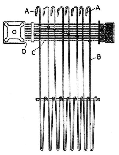
FIG. 70.—DETAIL OF A JACQUARD LOOM
INVENTION OF THE KNITTING MACHINE
We are wont to call Necessity the Mother of Invention; in many cases Laziness has given rise to valuable inventions, but according to legend, Cupid[283] played the leading rôle in the development of the knitting machine. It is said that in 1589 William Lee of England fell in love, but the girl who was the object of his devotion was always so busy with her knitting that she could not give him the attention he sought or thought he deserved. However, Lee was not to be thwarted in this fashion, so he built a machine to do the knitting in order that the girl could devote herself more completely to him.
There is another less pleasant version of the story to the effect that Lee became so attached to his knitting machine that he neglected the girl. However, in either case, love was somehow mixed up in the invention of the knitting machine.
We are not going to attempt to delve into the complicated mechanism of a modern knitting machine, but will merely call attention to the fact that modern machines perform automatically practically all the movements of the human hand in hand knitting.
The tendency of modern machinery has been to relieve the housewife of the tedious work she formerly performed and to take such work away from the home to the factory. There is one important machine, however, which has been introduced into the home, apparently to stay; for in the majority of houses it is still considered indispensable. It is a fact that the introduction of labor-saving machinery into the household has, until recently, met with stern opposition on the part of the housewife. It is all the more remarkable, therefore, that in the middle of the nineteenth century the sewing machine began successfully to invade the home.
HOWE’S INVENTION OF THE SEWING MACHINE
It was in 1844 that Elias Howe hit upon the brilliant idea of putting an eye at the point of a needle. This enabled him to produce a successful sewing machine, because it was unnecessary for him to pass the needle completely through the cloth in order to pull the thread through it. When the needle point penetrated the cloth a shuttle passed through the loop of thread that was carried through with the point. This shuttle carried a second thread which interlocked with the thread of the needle forming what is known as a “lock stitch.” In Howe’s machine the cloth was held vertically and the needle which was curved was carried by a lever. The needle was driven through the cloth with a swinging motion, somewhat like that of a pick-ax. The shuttle was driven back and forth by a pair of strikers after the manner of the flying shuttle of a loom. George Fisher, a friend of Howe, furnished $500 with which the first successful machine was built in 1845, and with this machine Howe sewed two suits of clothes, one for Mr. Fisher and the other for himself. A public exhibition was held at which the machine, crude as it was, beat five of the best hand-sewers that could be found. In 1863 Howe was reaping a fortune in royalties from his machine which were estimated at $4,000 per day.
The next notable improvement in sewing machinery was that of the rotary bobbin, invented by A. B. Wilson, which was patented in 1852. This did away with the flying shuttle and simplified the machine considerably. It made the sewing machine comparatively quiet, thus adapting it for domestic[285] use. In Wilson’s machine, a rotating hook passed through the loop of thread and carried it around the bobbin on which the lower thread was wound. Wilson also invented the four-motion feed for feeding the cloth under the needle. Sewing machines up to that time had been operated by hand, but Isaac Merritt Singer introduced a foot-power machine and by progressive business methods built up a thriving industry and did much to establish the sewing machine, not only at home, but abroad as well.
THE SINGLE-THREAD SEWING MACHINE
The single-thread machine was invented by a Virginia farmer who had never seen a sewing machine. James E. A. Gibbs had seen a picture of a sewing machine and, unaware of the fact that there was a shuttle carrying a second thread on the rear, or under side of the cloth, fell to puzzling over the problem of what happened to the thread carried by the needle through the cloth. Somehow, it seemed to him, the loop of thread must be held until the next stitch carried another loop of thread through it, thus forming a chain stitch. This led him to invent an ingenious revolving hook. With infinite patience he whittled out a model of his invention, and it is this hook that is the outstanding feature of the Wilcox and Gibbs machine.
MACHINE-MADE EMBROIDERIES
A notable modern development of the sewing machine is its adaptation to the making of embroideries and even laces. In the common domestic sewing machine the cloth is fed step by step under the needle, and the length of the step regulates the[286] size or length of the stitches. The feed may be set for short or long stitches. It is evident that if a greater range of length of stitch were provided, and if, while the machine was operating, the stitch could be varied at will, not only in length but in the direction as well, it would be possible to work out elaborate patterns of embroidery. This is what is done on the power-driven embroidery machines. Like the original Howe machine, the cloth is held vertically and a series of needles are used which pass horizontally through the cloth. As the needle retreats, the thread it carries forms a loop on the rear or “wrong” side of the cloth, and through this a shuttle is driven which carries a thread wound upon a bobbin. Between stitches the cloth is moved this way and that, in accordance with a prearranged pattern, and thus the design is embroidered. A single machine may have several hundred needles and, as they all work in unison, each needle repeats the design. The arrangement is such that one needle starts where the next one leaves off, so that the embroidery is continuous. The shuttles which operate on the wrong side of the cloth are small, boat-shaped parts which the Swiss have named “schiffli” or “little ships,” and this name has come to be applied to the whole machine.
The guiding of the cloth to produce the required design is accomplished either by hand or automatically. In the hand-guided schiffli machine a skilled “stitcher” seated at one side of the machine operates a pantagraph, tracing an enlarged design mounted on a board before him. As he moves the lever vertically and horizontally the frame carrying the cloth is correspondingly moved before the needles. An expert stitcher can put a great deal[287] of individuality into the work, which is impossible in the strictly automatic machine; accordingly the pantagraph is used for the finer grades of embroideries. In the automatic machines a perforated roll like that of a piano player is used. The perforations control the movements of the frame that carries the fabric.
FINE NEEDLEWORK BY MACHINE
These machines are of Swiss and German design, but American inventors have recently developed a machine for producing fine needlework which imitates very closely the work of the hand. In this machine the needle passes completely through the fabric as in ordinary hand sewing, but it does not have to be turned around for the return stitch because it is pointed at each end and has the eye in the middle. The needles are held by spring clips in a swinging frame. When the frame swings toward the cloth the needles are pushed through the fabric and their points are caught by spring clips in a frame on the opposite side. The latter frame draws the needles completely through and a set of hooks catch the thread and pull the stitch taut. The advantage of this type of machine is that it produces the same design on each side of the cloth; in other words, there is no “wrong” side to the embroidery. The design is controlled by a “stitcher” operating a pantagraphic system of levers and by skillful manipulation he can completely overcome the flat machinelike appearance of the automatic schiffli machine.
Laces are very ingeniously produced on schiffli machines by using the “burnt-out” system invented forty years ago by a German, named Beckel. This[288] consists in the use of thread of a different material from that of the fabric, and after the embroidery is completed the fabric is removed either chemically or by the application of heat, leaving only the stitching, which forms a delicate lace. For instance, cotton thread may be embroidered on a groundwork of wool, or silk thread is used on a fabric of cotton. Laces made in this way are known as Plauen laces, taking their name from the city where Beckel invented the process, and they form a large part of the machine-made laces that are now so widely used.
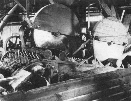
SAWING LOGS INTO 16-INCH LENGTHS PRIOR TO GRINDING THEM INTO PULP
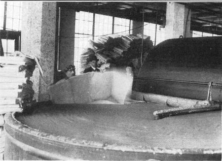
Copyright Kadel & Herbert
THE HEATER IN A PULP MILL WHERE THE WOOD PULP IS MIXED WITH CLAY
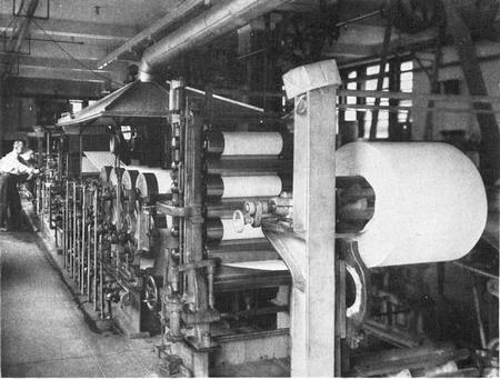
A MODERN FOURDRINIER PAPER-MAKING MACHINE
CHAPTER XVIII
THE MAKING OF PAPER
THE MAKING of paper is closely related to that of textiles. In each case the same basic materials are used. A mass of interlacing fibers is formed into a continuous sheet, but the method of interlacing the fibers and holding them together is entirely different. Paper resembles felt more closely than any other form of fabric. The fibers are not woven but are matted together and compressed. In the case of felt the fibers of wool or hair are held together mainly by the microscopic barbs that they possess while paper fibers are held together by means of sizing.
Although paper gets its name from papyrus the latter was not paper, for it was a felt of pith rather than fiber. The ancients produced a very fair writing material from the rushlike plants that grew in the swamps along the Nile. The stem of the papyrus was stripped of its bark and the pith was cut into thin ribbons which were laid side by side to form a sheet. Over these and at right angles to them was laid another layer of pith ribbons. The material was then soaked in water, pressed into a continuous sheet and dried. These sheets were then pasted together and rolled up into scrolls. Unquestionably they played a most important part in the civilization of ancient Egypt, providing, as they did, a[290] ready means of recording knowledge and disseminating it among the people.
CHINESE INVENTION OF PAPER
Like so many inventions that are of vital importance to modern civilization, paper is a Chinese invention. The Chinese made paper from the fibers of trees, a material to which we have reverted in recent years. The invention dates from about 150 A. D., when some one devised a process of reducing the bark of the mulberry tree to a pulp, beating it and boiling it in lye and then matting the fibers on a screen and pressing them into a finished sheet. The process was introduced into Europe by the crusaders in the 12th Century. In 1150 a paper-making plant was established in Italy and soon the new writing material was being made in increasing quantities and became a common article throughout Europe. It was not until the end of the 18th Century that machinery for making paper came into use.
In the old hand process which is still used to a very limited extent for special papers, the pulp, after being reduced to a thin milky fluid, was dipped out of a vat with a rectangular sieve which had a wire screen bottom of fine mesh. The water drained off, leaving the fibers upon the screen. As the pulp was draining the sieve was shaken about to distribute the fibers evenly and interlace them as much as possible. The depth of the sieve determined the amount of pulp that was dipped out and hence the thickness of the paper. The soft, matted mass of fibers was turned out upon a felt mat and left to dry. Soon other fibers came to be used and the finest grades of paper were made from linen and cotton rags. The rags were carefully sorted out and[291] washed after which they were stored in a damp place to rot for a number of weeks. Then they were cut and shredded and boiled until they were converted into a pulp. The complete process of making fine paper by hand took from two to three months. Paper was made in small sheets limited by the size of sieve that could readily be operated by hand.
The first man to make a continuous web of paper was Nicholas Louis Robert, a Frenchman who received a reward of 8,000 francs from his government for his invention. Robert’s patent rights were acquired by the Fourdrinier Brothers (Henry and Sealy), of England. They developed and perfected the machine and to them is ascribed the honor of founding the modern paper industry.
USES OF PAPER
Paper is more commonly and extensively used to-day than any other product of manufacture and is employed for an astonishing variety of purposes, ranging from milk bottles to suits of clothing. One very novel use we might mention, in passing, is to be found on the sugar plantations of Hawaii. After the cane is planted the fields are covered with a thick paper made, by the way, from sugar-cane fiber. This covering prevents the weeds from growing, but the sharp spikes of the sugar sprouts pierce the paper and grow through it. By the time the paper has disintegrated and the weeds have a chance to grow, the cane has such a start on them that they are kept shaded and cannot compete with or choke out the cane.
TURNING FORESTS INTO PULP
Before we proceed to describe the modern Fourdrinier machine, we must look into present day[292] methods of preparing pulp. The finest papers are still made from linen and cotton rags. Esparto grass is largely used in Europe. This comes from Spain and North Africa. But by far the greater part of the paper produced to-day is made from the fiber of trees. Particularly is this true of our own country, which consumes half of the world’s output of paper.
It used to be that only the poorest grades of paper were made from wood pulp; now however not only newspapers but nearly all books and magazines are printed on a forest product. Formerly only spruce wood was considered suitable for paper manufacture, but the rapid depletion of this raw material led to the employment of many other species of trees and our Government scientists are constantly searching for and experimenting with new woods for this purpose.
Because of the insatiable appetites of our large newspaper printing presses and because a newspaper is not intended to be an imperishable document but a fleeting record of passing events, quality is of little importance in the preparation of pulp for newsprint and everything must be sacrificed for speed. The pulp is made of “ground” wood as distinguished from the chemically prepared wood pulp known as “sulphite.” The wood is first stripped of its bark and then cut into pieces running from two to four feet in length, depending upon the size of the magazine of the grinder. The wood is pressed against a revolving grindstone by hydraulic pressure and at such an angle that the fibers torn off will be as long as possible. The fibers are borne off by a stream of water which carries them through a set of screens. These remove any unground slivers,[293] and eventually the pulp is drained of water and pressed into laps, or, if it is to be used immediately, it goes directly to the beating engine. Here it is mixed with a certain amount of “sulphite pulp,” usually from 20 to 25 per cent. To correct the yellowish color of the pulp, a small amount of blue and red coloring is added. To give body to the paper from 5 to 15 per cent of clay is mixed into the pulp and, to bind the fibers together and give the paper a finish that will be at least partly nonabsorbent, a quantity of rosin and soda ash is added with enough alum to precipitate the rosin upon the fibers. The beater thoroughly mixes the mass of material and converts it into a fluid of the consistency of thin milk, which then passes on to the Fourdrinier machine.
GETTING DOWN TO THE “BONES” OF THE WOOD
Paper made from ground wood pulp soon discolors and becomes brittle owing to the presence of the lignin and resin of the tree. The superiority of sulphite pulp is due to the fact that chemical processes are used to remove these disturbing ingredients, leaving only the “bones” of the tree, that is, the pure cellulose fiber. Spruce wood is usually used and after being freed of its bark and thoroughly cleaned, all knots are cut out and it is sawed into short lengths which are then split and cut up into little chips from ¼ to ½ inch long. These chips are boiled under pressure in a solution of sulphur dioxide and slaked lime. The “digesters” in which the chips are boiled are large steel cylinders lined with brick set in cement and coated with litharge and glycerin, so as to prevent the sulphite liquor from coming into contact with the metal. A[294] steam pressure of seventy to eighty pounds is maintained for eight to ten hours and then the digesters are discharged into vats. The sulphite liquor in which the resinous matter is dissolved is drained away and the pulp is washed.
Soft woods, such as poplar, basswood, etc., are boiled in caustic soda, producing what is known as “soda pulp.” “Sulphate pulp” is made by boiling in a solution of sodium sulphate, to which a certain amount of sodium carbonate and caustic soda are added. This process is used for producing pulp for so-called “Kraft” paper and brown wrapping paper.
Formerly pulp was always made in the paper mill and hence the mills had to be located near the source of wood supply, but to-day the making of pulp is carried on as an independent industry in remote forest regions where water power is plentiful. The pulp is pressed into laps and compressed into bales weighing about 400 pounds. These are sent over long distances by rail or steamship to paper mills located in or near the big cities, so that the paper may be made near the points of consumption.
Baled paper pulp has to be reconverted into a smooth milklike fluid. A shredding machine is used for this purpose, which tears the pulp apart and mixes it with water. Then it goes to the beater where it receives its quota of sulphite pulp, coloring matter, clay, and sizing, as explained before. After an hour of treatment in the beater, it passes on to a tank in which it is further diluted with water and is then put through a Jordan engine. This consists of a conical cylinder in which is placed a conical roll. Both cylinder and roll are formed with[295] knives that extend longitudinally, but the revolving knives are set at a slight angle to the fixed knives, somewhat after the fashion of a lawn mower. The conical form permits of careful adjustment of the roller in the cylinder. The pulp mixture enters at the smaller end and discharges at the larger end. This machine gives the pulp its final beating and reduces it to a very smooth consistency.
THE FOURDRINIER PAPER-MAKING MACHINE
From the Jordan engine the pulp is passed on into the Fourdrinier machine, which we are now ready to investigate. The principal element of this machine is a traveling belt of copper wire gauze which takes the place of the screen or sieve used in the hand process. To confine the pulp to the belt there are two endless bands of rubber, known as “deckles,” along each edge of the screen, which travel with the screen. To insure proper interlacing of the fibers, as in the hand process, the screen is shaken laterally at the rate of about 300 vibrations per minute.
The fluid pulp enters the machine through a flow box, where a constant hydraulic head is maintained, so as to preserve a uniform discharge to the wire gauze. The milky stream issues through a narrow opening in the flow box, known as a “slicer.” This may be adjusted to alter the width and also the thickness of the stream. No one would suspect from the appearance of the milky fluid that it is filled with fibers, but a microscopic examination of a drop of the thin liquid shows that it is filled with tiny particles floating in the water like logs in a river. It is interesting to watch this stream, as it passes out upon the screen, change magically before[296] one’s eyes, from a milky stream into solid mass of pulp.

FIG. 71.—DIAGRAMMATIC VIEW OF THE FOURDRINIER PAPER-MAKING MACHINE
| A. Flow Box | EE. Pulleys | I. The Final Suction Box for Drying |
| B. Copper Gauze Belt | FF. Drums | J. Couch Roll |
| C. Rollers | G. Suction Boxes | K. Canvas Belt |
| D. Deckles Confining Pulp | H. Dandy Roll |
In Figure 71, which is a diagrammatical view of a portion of a Fourdrinier machine, the flow box is shown at A and the copper gauze belt at B. This belt is supported on a series of rollers, C. The deckles which confine the pulp along the margins of the screen are shown at D. These belts travel with the wire gauze for a certain distance and then pass back over the pulleys, EE, while the wire cloth passes on and around the drums, FF. As soon as the pulp flows out upon the wire gauze, the water it contains begins to drain away through the gauze. But it does not do this fast enough under the mere pull of gravity and it must be helped by means of suction. At GG there are boxes or troughs that fit against the under side of the wire gauze. In them a partial vacuum is maintained by means of suction pumps and a large part of the water remaining in the pulp is sucked out here. A dandy roll is shown at H, which presses lightly upon the moist pulp, squeezing out the moisture in it, and at I there is a final suction box which further dries the web of fibers. It is the dandy roll that puts a patterned surface on the paper. If the face of the dandy roll is of finely woven wire cloth with diagonal mesh, a “wove” paper is produced, while if it is of such surface as to impress parallel lines in the half-formed paper, “laid” paper is produced. Water marks are also produced by placing a suitable raised or depressed pattern on the dandy roll, producing a corresponding thickening or thinning of the pulp. Even after passing the last suction box, the thin web of paper is still very wet and so flimsy that it cannot be handled. Right here comes the most delicate part of the whole process. The web must be picked off the wire cloth and carried across a narrow gap to a felt belt which conducts it through another set of rollers, A felt-covered roll, J, known as a “couch” roll, presses down upon the web and the latter clings to the felt in place of the wire cloth which passes down around the roller F. In starting a web of paper very skillful manipulation is required to transfer the web from the couch roll to the felt belt, but after it has once bridged the gap it has enough tensional strength to pull itself across the gap. The felt belt carries the web through a pair of heavy rollers which press out more of the water. Because[298] the paper passes through the rolls with the felt belt it receives an impression from the felt on the under side. This is now corrected by running the paper through a second pair of rolls in the reverse direction, and on a second felt belt, so that both sides of the paper receive the same impression. From here on the paper passes through a long series of steam-heated drying rolls and emerges eventually as a perfectly dry sheet.
Our largest Fourdrinier machines make a web 200 inches wide and they can be run at a rate of 800 feet per minute, or more than nine miles per hour. The paper is made in lengths eight miles long, which are wound up into rolls to be fed into the huge printing presses of our metropolitan newspaper plants.
The difference between the making of news print and finer papers lies chiefly in the quality of pulp used and the quantity of clay and sizing added. After the finer grades have issued from the drying rolls, they are put through calenders to give them a glazed surface. This consists virtually in ironing the paper between smooth rolls of iron on one side and compressed paper or cotton on the other. Just as in ironing clothes, the paper must be moistened before being ironed and steam is used to supply the necessary moisture. In some cases a high glaze is given to one side only of the paper by means of friction. The paper passes between two rollers of different size. The smaller one travels faster than the larger one and consequently it slips on the paper, giving it a very smooth surface.
THE CYLINDER MACHINE FOR MAKING PAPER
There is another type of paper-making machine which is used for coarse papers, pasteboard, etc.[299] This is known as a cylinder machine. The wire gauze is formed into a cylinder which revolves in the liquid pulp. A slight suction is maintained in the cylinder which causes the water to flow in through the gauze; leaving the fiber drained on the surface. The cylinder revolves, carrying the drained pulp on its surface until it encounters a felt roll that picks off the web and carries it to the pressing and drying rolls. One disadvantage of this type of machine is that the cylinder in dragging the drained pulp through the water causes the fibers to be combed in a direction parallel to the run of the paper web, so that the paper, while strong in the direction of its length, is comparatively weak in the transverse direction. This is corrected to a certain degree by the use of “riffles” or devices that produce eddies which disturb the even flow of the pulp.
In the making of pasteboard, a number of cylinders contribute their webs to form a single sheet of several plies.
CHAPTER XIX
TYPESETTING AND PRINTING MACHINERY
“WHO WON the war?” The question immediately brings forth numerous contenders who claim the honor, respectively, for the aviator, the chemist, the engineer, the mechanic, the farmer, the shipbuilder, etc. As a matter of fact, all these and many others as well were invaluable contributors to the final success, and “there is glory enough for all.”
The question, “What branch of technology or what branch of machinery has done most for civilization?” finds a similar division of opinion, with partisans in favor of the steam engine, machine tools, electrical machinery, iron manufacture, paper making, printing, etc. Again, it is clearly evident that all have been most valuable contributors and none may carry off all the honors. However, partisans of the printing press are entitled to place that machine among the foremost because it has certainly been most useful in preserving and disseminating all classes of knowledge and in promoting the progress of civilization.
EARLY CHINESE PRINTING
It is hardly necessary for us to refer to Johann Gutenberg’s invention in 1436 of separate type for each letter. Many centuries before that the Chinese[301] had made wood engravings of complete pages and printed them on paper. Their method was to prepare an ink copy on a sheet of paper and then transfer the copy by pressing the paper on the wood before the ink was dry, after which they carved away all the surface except those parts which were inked. This gave them a reverse plate from which any number of copies could be printed. The invention of individual type which could be used over and over again for setting new copy was a marked improvement over the Chinese system.
DEVELOPMENT OF PRINTING PRESSES
The primitive screw press saw little improvement except in minor details down to the end of the eighteenth century. Then steam began to take the place of hand power and the idea was conceived of using a rotary cylinder in place of a flat press. The types were tapered so that they could be fitted about a cylinder. The paper was fed between the type cylinder and a soft impression cylinder faced with leather. The ink was applied to the type by means of a roller which was fed by an inking apparatus.
In 1814 two rotary presses were installed in the offices of the London “Times,” making it possible to turn out that newspaper at the marvelous rate of 11,000 impressions per hour. In this country, Richard Marsh Hoe invented a machine in which four, six, eight, or ten impression cylinders operated on a single form of type, thereby increasing the output of the press correspondingly. The first machine, a four-impression cylinder press, was used by the Philadelphia “Ledger” in 1846, and it printed 8,000 papers per hour.
Next came the “perfecting” press that printed on both sides of the paper, and then came the continuous web press, in which the paper was fed from a roll as a continuous sheet and, after receiving the type impression, was cut, folded, and delivered as a complete newspaper.
THE STEREOTYPE PLATE
Meanwhile stereotyping was introduced into newspaper printing. In stereotyping an impression in plastic material is made of the type face and then a casting is made from this impression which, of course, exactly duplicates the type face. The type is thus relieved from wear in the press and it is immediately released for use in setting up other copy while the printing is done from the stereotype plate. While the use of stereotyping in book printing dates back to the eighteenth century, it was not thought practicable for newspaper printing because of the length of time taken in making the plate, but in 1861 papier-maché was introduced as a matrix material and a system of rapidly drying the mold was developed so that a plate could be cast in a comparatively short time; furthermore, impressions could be made from a flat face of type and then the mold could be bent so as to make curved stereotype plates for use on the cylinder presses. In newspaper work it takes but five minutes to make a stereotype plate. Stereotype metal does not stand the wear of printing very long and the plates must be renewed from time to time. This fits in well with newspaper requirements because clean cut work is not called for, and as the news keeps coming in new editions must constantly be printed, which means that new plates must be[303] made from time to time. For the finer printing of magazines and books, copper-faced electrotype plates are used in place of the soft stereotype plates of newspaper printing.
MODERN NEWSPAPER PRESSES
A modern large newspaper press is a bewildering sight to behold; there is such a vast number of rolls and cylinders, and the web of paper moves so rapidly. But, after all, the machine is multiplex rather than complex. It consists of a large number of printing cylinders, all operating in a single frame. Take, for instance, a double-octuple, color-combination press. It consists really of two separate presses, each operating on four webs of paper that feed from opposite ends toward the middle. There are two type cylinders for each web, one for each side of the paper. Each cylinder is long enough to take four stereotype plates side by side, and since each plate extends but half way around the cylinder we have eight pages printed on each side of the web. This makes sixteen pages per web or sixty-four for each half of the machine, giving a total of 128 page impressions at each turn of the cylinders. It is seldom that a 64-page paper is required, hence the webs are slit in two by a revolving knife blade and each section of the press has two folding mechanisms so that two sets of 16-page papers are printed, folded, and delivered by each section. Arrangements are provided whereby the product may consist of 32-page papers. The papers are delivered by a traveling conveyor and every fiftieth paper is pushed out ahead of the others so as to provide a simple method of keeping count of the product.
PRINTING 240,000 PAGES PER HOUR
The cylinders turn at the rate of 300 revolutions per minute which means that the paper runs through the machine at nearly 14 miles per hour. Summing up all the webs we have a total consumption of 108 miles of paper per hour. The paper is 6 feet wide and the weight of paper in an hour’s run is about 18 tons and the hourly production is 150,000 sixteen-page papers. When color is used, the press will deliver 50,000 24-page papers per hour with the two outside pages printed in three colors and black. The course of the color printed web must necessarily be different from that of the plain black printed web. It must pass through a number of printings; and to prevent the moist ink from transferring to the impression rolls and from them back to a succeeding page, thus soiling or blurring the impression, an extra roll of thin paper is passed between the printed web and the impression cylinders. This acts in a measure as a blotter. The offset paper is taken up on a roll and used over and over again. It is used not only for color work, but also when fine half tone engravings are to be printed so that a cleaner impression may be obtained.
The inking system of printing press is very elaborate. It is highly essential that the ink be spread upon the type surface in just sufficient quantity to be picked up by the paper and that the ink be uniformly distributed over the whole surface. There is an ink reservoir and a set of inking rollers for each cylinder. The reservoir consists of a trough running the whole length of the cylinder. At each turn a revolving roller dips into the ink[305] and transfers a thin film of ink to a series of small rollers. These are grouped about a large roller to which they deliver the ink. The small rollers have an axial reciprocating motion whereby the ink is uniformly spread over the large roller. The latter transfers its thin coating of ink to a pair of rollers known as “form rollers” and these in turn deliver the ink to the printing cylinder.
A SEA CAPTAIN’S CONTRIBUTION
The folding mechanism of a printing press is interesting. The paper is first fed over a wedge-shaped form which folds the paper lengthwise and then it is given a cross-wise fold. Curiously enough the folding mechanism for printing presses was first invented by a Yankee sea captain, named Cromwell, who could not read a drawing but developed his invention by whittling out wooden models. He also contributed other valuable improvements for the printing press worked out in the same primitive way.
The rotary press was evolved especially for the printing of daily papers and for a long time magazines continued to be printed on flat-bed presses. But as the circulation of magazines grew into the hundreds of thousands it became necessary to build high speed presses to turn out these large editions. Accordingly rotary machines were constructed similar in design to newspaper presses, but with refinements to enable them to produce the better class of work required of magazine printing. Although there are many magazines still printed on flat bed presses, particularly those which publish small editions of less than a hundred thousand, all the big national weekly journals and monthly[306] magazines are printed on rotary presses and some of them even use web presses.
GATHERING AND BINDING MAGAZINES
When a newspaper leaves the press it is folded, cut, and ready for the news stand. Not so with the book and magazine press. There are too many pages to be handled by a single press, and, furthermore, the pages must be bound together. Some large magazines contain regularly more than 500 pages and occasionally they will run over a thousand pages. Obviously no single press could handle so many pages and it takes the product of many presses to make up a single copy. Each press prints what is known as a form or signature and these signatures from the different presses are then gathered, wire-stitched, and bound into individual copies. There are machines which will do this work of gathering and binding at the rate of sixty 1,000-page magazines or catalogues every minute. The machines are adjustable for pages of different dimensions. The forms may consist of four, eight, sixteen, or thirty-two pages. A separate compartment is provided for each signature. A large machine will handle thirty-six 32-page signatures. The compartments are kept supplied by an operator, there being usually six compartments for each operator to attend to. The bottom signature in each compartment is brought into position by a suction device which seizes the signature and draws it out, depositing it in a steel trough. Here a belt conveyor moves the signature along at the right speed to carry it before the next compartment just as a signature is being withdrawn therefrom. Thus the magazine or book is progressively built up and the[307] signatures reach the end of their course properly assembled. A very delicate adjustment is provided to insure the proper adjustment of signatures. The grippers are adjusted to receive signatures of a certain thickness. If the operator should make a mistake and put a signature of a wrong size in the compartment the whole machine would come to a standstill. The adjustment is so delicate that even a variation of a single thickness of paper is enough to operate the stop mechanism. Each assembly of signatures as it reaches the end of the trough is squared up and then bound with wire stitching. From this point it moves on to receive its cover. A thin coating of hot glue is applied to the rear edge of the signatures. The cover is automatically applied and firmly pressed into place. The finished book is then carried on out of the machine and deposited neatly on a pile of previously bound books. To operate such a machine there are required one chief operator and an assistant and six girls to feed the signatures to the compartments.
SETTING TYPE BY MACHINE
The publication of a modern daily newspaper with its many special editions would be well nigh impossible if we still had to depend upon hand setting of type. Tens of thousands of type characters are required to make up a single newspaper page, and although skilled hand compositors work with extreme rapidity it would take a large corps of men to set type for even a small newspaper in the short time available. Speed is of prime importance in newspaper work and the task of handling thousands of little pieces of type metal and arranging them correctly into words and sentences was[308] long recognized as a serious handicap, but the problem of doing this work by machine was by no means simple one and baffled inventors for years. One of the principal difficulties lay in the size and shape of the type and another was that of justifying the lines, that is, providing just the right width of spaces between words to fill out the lines completely so that they would all be of equal length, giving a straight instead of a ragged margin to the column. After that came the problem of redistributing the type.
The first really successful composing machine was the invention of Ottmar Mergenthaler in 1888. Mergenthaler overcame the difficulties that had balked other inventors by attacking the problem from a radically new angle. Instead of setting precast type, his machine cast its own type from a set of matrices. By operating a keyboard, the matrices were assembled in a line which was justified automatically after the line was composed and then the whole line of type was cast in a single slug. Hence his machine earned the name “linotype.” Then the matrices were returned automatically distributed to the proper channels of the matrix magazine ready to be used over again for succeeding slugs.
THE LINOTYPE MATRIX AND SPACE BAR
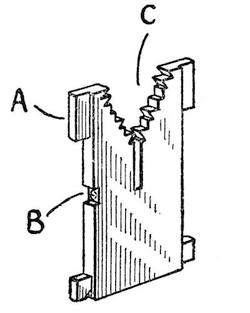
FIG. 72—A LINOTYPE MATRIX
A picture of a linotype matrix is shown in Figure 72. It is a plate of brass formed with ears A at the four corners. The type mold is shown at B and of course the thickness of the matrix varies with the width of the type letter it is designed to cast. In the top of the matrix there is a V-shaped slot C formed with teeth which are designed to engage grooves in a V-shaped bar over the matrix magazine. The teeth on the matrices are variously cut away and serve as keys to the different channels of the magazine. There is a different combination of teeth for each letter of the alphabet and all matrices of the same letter have the same combination of teeth. The teeth on the distributing bar are also cut away according to various combinations. After the line has been cast the matrices are all raised by their ears and fed one by one upon the distributing bar. Each matrix moves along until it arrives over the channel it is designed to enter when it comes to a gap in the teeth of the bar that are supporting it and drops into the magazine. Although there are but seven teeth on each side of the V-shaped bar, there are more than enough combinations possible to provide a characteristic one for every key of the keyboard. A matrix always has at least one pair of teeth in engagement with the bar until it reaches the gap that lets it fall into its own special channel of the magazine. The number[310] of matrices of each character varies with the normal frequency of use of that letter. For instance, the letter e is very commonly used, and there must be many more e matrices than z matrices, but in any case the number need not be very large because the process of casting a line and redistributing the type does not take very long and the matrices are soon back in the magazine ready to be used over again. The casting and distributing operations are entirely automatic and while they are in process the compositor is setting a new line.
The method of spacing which was a later development of the linotype is also very ingenious. The compositor does not have to bother with the width of spaces required to fill out a line. He merely touches the space key at the end of each word and and a space bar drops into place. Each space bar is formed of a pair of wedges and after the line has been assembled the space bars are automatically expanded to fill out the line completely by mechanism which holds down one wedge member (A, Figure 73) and slides up the other (B).
INDIVIDUAL TYPE CASTING AND COMPOSING
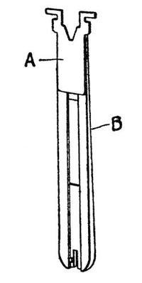
FIG. 73.—A LINOTYPE SPACE BAR
The difficulties of casting the linotype slug proved a serious handicap in the earlier days of the linotype. The product of the machine could not compare in quality with precast hand-set individual type, although it served very well for newspapers; but the machine is now so far perfected that it is widely used for magazine and book composition. However before this stage of perfection was reached the demand for a machine that could do a higher grade of work led to the invention of another machine known as the “monotype.” The monotype consists actually of two machines, one of which is operated by a compositor and the other operated entirely automatically by the product of the first machine. The compositor operates a keyboard and thereby cuts perforations in a long strip of paper. These perforations are arranged in characteristic groups one for each key. The perforated paper is then run through the second machine and in accordance with the various perforations the separate types are cast and assembled into justified lines. Air flowing through the perforations operates a pneumatic mechanism which brings the proper molds into position and casts the separate types. The method of justifying the lines is very interesting. As in the linotype the operator merely touches a space key at the end of each word, but at the end of the line the mechanism automatically estimates the spaces to be filled and divides this by the number of spaces so that a characteristic group of perforations is punched when the compositor shifts to[312] the next line. In the casting machine the paper ribbon runs through backward and the space group of perforations is encountered before the line is cast. This automatically adjusts the mechanism to cast spaces of the requisite size to fill out the line exactly.
WRITING BY MACHINE
In one sense we have taken up the various machines employed in printing in reverse order. Of course the first machine used is the typewriter, after which comes the composing machine, and finally the press.
It was in 1866 that two inventors, C. Latham Sholes and Samuel W. Soule, undertook to make a machine for printing numbers in serial order upon the pages of a blankbook. Carlos Glidden, another inventor, who was engaged in developing a spading machine designed to take the place of a plow, saw their work and suggested that they make their machine write letters and words as well as numbers. The three combined and proceeded to evolve the new machine. By the end of the summer of 1867 they had produced a typewriting machine that could be operated fairly rapidly and that produced fair work. It was one of the letters written by this machine that brought James Densmore into the enterprise. He furnished the money needed to improve the crude typewriter and make it a commercial machine. Many models were built but nothing was produced that seemed good enough for commercial production. This development work was too slow and discouraging for Soule and Glidden and they dropped out, but Sholes inspired by Densmore persevered until at last in 1873 he had produced a machine which he could offer for manufacture.[313] The typewriter was then taken to the Remington factory at Ilion, N. Y., and the next year it was placed on the market and began its public career.
Such is the story of the early development of the typewriter. It has become so widely used and is so indispensable a part of the business office that it arouses the utmost astonishment to learn that there still are a few old-fashioned houses so conservative and so far behind that they continue to write their business letters with the pen. So common a machine, it is hardly necessary for us to describe in detail except to mention two steps in the development of the machine, namely the arrangement of the type bars whereby the typewriting is visible to the typist, and secondly the effort to overcome noise by limiting the stroke of the type bar and making it impinge upon the paper with a pressure stroke rather than a hammer blow.
A recent development is the “stenotype,” a small machine which prints shorthand characters, thus expediting the taking of rapid dictation.
CHAPTER XX
CAST IRON, WROUGHT IRON, AND STEEL
IT USED to be that wars were fought for gold, but nowadays the possession of rich iron mines is enough to arouse the cupidity of neighboring nations less favored by nature. In fact, even though an ounce of gold is worth twice as much as a ton of iron, the value of the iron we dig out of the earth each year is far greater than that of gold. When that rough ore is converted into iron and steel and then into thousands of useful articles, its value mounts so high that it cannot be estimated. The qualities of iron and its alloys are so excellent and so varied under different treatment that this metal may truly be said to form the foundation of all our mechanical progress. On the one hand it spans our wide rivers, carries the burden of heavy freight trains, or, in the form of armor plate, resists the terrific impact of high-powered shells; on the other hand the same metal, spun into a hair spring, governs the ship’s chronometer, or, in the compass, points a trembling finger to guide the navigator on his course.
IRON IN ANCIENT DAYS
The first use of iron in the service of man dates far back into the ages. An iron tool was found in the pyramid of Kephron which must have been[315] used 3,500 years before Christ. However, because of the difficulty of working it, iron was not extensively employed except for swords and cutlery. The conversion of iron into steel and the tempering of steel blades grew to be an art which gave Damascus and Toledo a world-wide reputation that dates back over a thousand years.
The ancients used to smelt their iron ore in what was known as a Catalan forge because of its extensive use in Catalonia, Spain. Whether the forge was invented there or not we cannot say. Similar forges have been found in India and other widely remote places. They comprised an inclined tray leading to a pot which formed the furnace and in which a charcoal fire was kindled. The ore and charcoal were placed on the tray and from time to time were raked down into the furnace and air was forced into the bottom of the furnace by means of bellows. In an improved form of the Catalan forge air was furnished by means of an air compressor operated by a stream of water. This has already been referred to and illustrated on page 90. Limestone served as a flux to melt the earthy matter. The iron obtained from these primitive furnaces was not heated sufficiently to flow as a stream, but was merely reduced to a pasty mass which was then hammered into shape by the blacksmith. Ten or twelve pounds of metal per day was considered a fair output for one of these forges.
DISCOVERY OF COKE
It was not until the middle of the 14th Century that a blast furnace, crudely similar to those we have to-day, was first built and with it a temperature was obtained that was high enough to turn the[316] metal into a liquid which could be cast in molds. Charcoal continued to be the fuel used until about four centuries later, when Abraham Darby discovered that by baking coal to remove its free gases, he could produce a new fuel known as coke which was a good substitute for charcoal. This gave a wonderful impetus to the iron industry in England where there were ample deposits of coal adjacent to the iron mines. Shortly after that, Mr. Henry Cort of Gasport, England, invented the processes of puddling and rolling the product of the blast furnace, thus converting the iron into a tough, malleable metal.
ALLOYS OF CARBON AND IRON
We must pause here to learn the difference between cast iron, wrought iron and steel. Iron, as we know, has a high affinity for oxygen. When exposed to air and moisture it oxidizes, rusts very quickly. The iron we find in nature is largely oxidized. In other words, it is rusty. It is also found in combination with other elements as well. The object of putting iron ore through a furnace is to rid it of oxygen and this is most readily accomplished by melting it in a carbon fire. The highly heated carbon combines with the oxygen and passes off as carbon dioxide and carbon monoxide gas. But a certain amount of carbon unites with the iron and it is this alloy of carbon and iron that makes cast iron so stiff and brittle. The less carbon present the softer is the metal and pure iron is very ductile.
It was to rid cast iron of its carbon content that Cort invented the puddling process. As the metal came out of the blast furnace it ran into a “reverberatory” furnace where, without coming[317] in contact with coke or other carbon fuel, it was exposed to flames from an adjoining furnace which burned out the carbon, and then the carbon-free iron was cast into large pieces known as blooms which were hammered to rid them of slag. The final product was known as wrought iron. Wrought iron then differs from cast iron in having no carbon. Steel, on the other hand, stands half way between wrought iron and cast iron in having a small percentage of carbon. How steel is made will be described later.
MECHANICAL HANDLING OF ORE
Of course machinery plays a large part in the modern iron industry. It would be an endless task even to load one of the big blast furnaces by hand and then the enormous output of molten metal—40 tons for every pound produced by the old Catalan furnaces—could not be handled without ponderous machines whose huge arms and fingers are not scorched and blistered by the intense heat. Along the Great Lakes vast loading machines fill the holds of ore vessels and at the plant there are enormous unloading machines that travel on rails. These have long bridgelike arms that reach out over the ore boat and drop huge clam-shell buckets into their holds. The buckets quickly unload the boats and dump the ore on shore where other buckets pick up the ore, carry it back and pile it up in big heaps that look like mounds of reddish earth.
THE MODERN BLAST FURNACE
Blast furnaces are towering cylindrical structures of steel lined with fire brick. They are loaded from the top with alternate layers of coke[318] and ore. Limestone also is added to act as a flux for the earthy matter, as explained above. Running around the furnace near the base there is a large pipe known as the “bustle” pipe. Through this air is fed to a set of “tuyeres” which lead to the base of the furnace and admit blasts of air requisite to maintain combustion at an intense heat. The gases of combustion are not allowed to escape freely into the atmosphere. The top of the furnace through which the ore and fuel is admitted is closed by an air lock and the flaming hot gases are led into “stoves” where they give up a large part of their heat to preheat the air which is pumped to the blast furnace. The gases being mainly composed of carbon monoxide are further combustible and may be used for heat, light, and power purposes. In fact, they are commonly used to drive the air compressors which feed the blast furnaces.
The blast furnace has two openings, one above the other. Through the upper one slag is drawn off while the molten iron which trickles down and collects at the bottom of the furnace is tapped off through a hole near the base of the furnace. The fiery stream pours out into a lot of small trough-shaped molds and is thus formed into “pigs.” These pigs are all connected to the main body of the metal stream and must be broken off. To save the time of cooling and of breaking off the pigs a machine is used which consists of a series of molds connected to form an endless belt. The molten iron is poured into these molds which in their course dip into a trough of water. Here the iron is cooled and solidified. The molds then run up an incline and finally dump the pigs directly into railway cars which haul them away.
BURNING OUT THE CARBON
The production of steel economically and on a large scale dates back to the inventions of Henry Bessemer. While searching for an improved method of making big guns, Bessemer hit upon the idea of forcing a blast of air through the molten iron and thus burning away carbon, silicon, and manganese in the cast iron. No fuel was supplied except the carbon and silicon in the iron itself. In burning out this carbon sufficient heat was generated to keep the metal fluid.
When Bessemer made the announcement of his new process before the British Association in 1856, his paper met with skepticism, but he was able to demonstrate by actual experiment that cast iron could be converted into malleable iron in this way. However, when several firms operating under licenses from the inventor endeavored to reproduce his experiment on a commercial scale they were unsuccessful, and after costly experiments the process was given up as a failure. Bessemer, however, persisted in his efforts and succeeded eventually in producing malleable iron of a quality equal if not superior to that on the market. But iron makers after the failure of the first experiments would have nothing to do with the new process until Bessemer began to turn out quantities of iron at $100 a ton below the prevailing market price. Then iron makers woke up and Bessemer had no difficulty in placing his process with numbers of firms on a very profitable royalty basis.
This process pertained to the making of iron and not steel. When Bessemer tried to produce steel he was confronted with serious difficulties. The steel[320] he obtained was very brittle. He tried purer ores with little better success. Then a solution of his problem was offered by Robert F. Mushet, who discovered a compound which would be added to the molten metal to purify it. This compound which is known as “spiegeleisen” is composed of iron, carbon, and manganese. It removes the oxide of iron and the sulphur and regulates the amount of carbon in the steel.
A Bessemer converter furnishes by far the most spectacular operation in steel manufacture. The converter consists of a large bottle-shaped vessel lined with refractory material. In the bottom of the vessel there are openings through which the air blast is admitted. The molten metal is poured into the flask and then the air blast is turned on. The metal begins to boil violently. A dazzlingly brilliant blast of flame and sparks comes roaring out of the mouth of the converter. Bubbles of metal are thrown high into the air where they burst into showers of sparks. The effect is similar to that of a volcanic eruption. In from ten to twenty minutes the eruption subsides and then a quantity of spiegeleisen is added. The converter is mounted on trunnions so that when the operation is completed the vessel is tilted over and the charge of molten metal now converted into steel is poured out.
OPEN HEARTH FURNACES
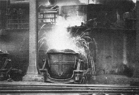
MOLTEN METAL FROM A BLAST FURNACE
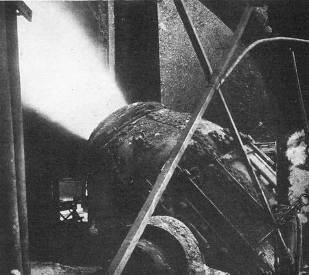
BESSEMER CONVERTER BLOWING AIR THROUGH A MASS OF MOLTEN IRON
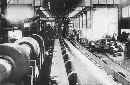
A STEEL BEAM PASSING THROUGH THE FINISHING ROLLS OF A STEEL MILL
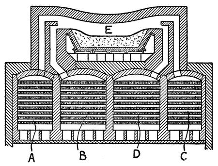
FIG. 74.—SECTIONAL VIEW OF A REGENERATIVE OPEN-HEARTH FURNACE
While the Bessemer converter provides a very economical and expeditious method of converting cast iron into steel, it is difficult to regulate the carbon content with great accuracy and hence the use of the open-hearth furnaces which furnish a slower method of burning out the carbon. Figure 74 is a diagrammatic representation of such a furnace. Below the hearth of the furnace there are two pairs of chambers, A, B and C, D, filled with a checkerwork of bricks. Gas is passed through one chamber A, and air through the other B, and they combine to form a very intense flame above the hearth E in which the metal is placed. The burnt gases pass over and through the other pair of chambers, C, D, on their way to the stack. By this means the bricks in the latter chambers are raised to a white heat. Then the process is reversed; air flows through the hot checkerwork of bricks in the chamber C and gas through the hot checkerwork in chamber D, and after combustion in the furnace the burnt gases are drawn through the bricks of the first pair of chambers. By alternating the direction[322] of flow the air and gas fed to the furnace are always preheated by the stored-up heat of the previously burned gases. While it takes but a few minutes to convert cast iron into steel in the Bessemer converter, the open-hearth process occupies from eight to twelve hours.
The steel produced in the open-hearth furnaces is poured into ingot molds. These are approximately rectangular in section and slightly larger at the bottom than at the top. They are open at the top and bottom, but at the bottom rest upon a base plate. As soon as the steel has hardened the plunger of a stripping machine holds down the glowing ingot while a pair of hooks lift off the mold, leaving the ingot resting on the base plate.
ROLLING INGOTS INTO RAILS
In the manufacture of railroad rails the ingots are placed on a traveling “table” consisting of a series of rapidly turning rollers. These carry the ingot to a pair of large steel rolls between which it passes. The rolls compress the ingot slightly and it is automatically turned over and passed through a second pair of rolls. After passing through four “stands” of rolls, turning over between each stand, it is considerably reduced in cross-sectional area and correspondingly lengthened. It is now termed a “bloom.” The bloom goes through a series of rollers which gradually reduce its section until it is some forty feet long. Then it is cut in two and each section passes through other rolls, until finally it is reduced to the required rail section. Each section is then about a hundred and twenty feet long and the glowing writhing rail passes on to the saws where it is cut into ten-yard lengths. A similar[323] process is employed in rolling other forms of rails and in making steel plates and sheets.
STEEL FOR BIG GUNS
The largest machines employed in the steel industry are those used for the manufacture of armor and big guns. A modern large high-powered gun is not a single solid casting or forging, but is made up of a series of steel tubes that are shrunk one upon another so that the inner tube is compressed. The reason for this is that the explosives used are so powerful that they would expand the inner tube or lining of the gun beyond its elastic limit and in that way enlarge the bore. By having it compressed to start with it can expand farther without exceeding the elastic limit. This expansion takes place so suddenly that the lining rebounds or returns to its original dimensions before the outer tubes have felt the full pressure and they too are thus prevented from being expanded too far. In some cases the compression is effected by winding the gun with a heavy wire of rectangular cross section.
SQUEEZING OUT THE “PIPES”
Steel for guns and armor is made in the open-hearth furnace where the quality of the metal may be regulated to a nicety. Gun tubes are cast in vertical molds and during the cooling of the ingot it is subjected to pressure so as to prevent segregation and the forming of “pipes.” Pipes are cavities that are liable to form in the center of the ingot due to contraction during cooling. Steel, as we have learned, is not pure iron, but an alloy, and the various constituents have different temperatures of solidifying, consequently they exhibit a tendency to[324] segregate. It is to overcome such tendencies that a so-called “fluid” compressor is used. This is virtually a hydraulic press with a plunger that bears down on the fluid metal as it is solidifying. Modern big guns are enormously large. A sixteen-inch 50-caliber gun, for instance, is nearly seventy feet long, consequently the ingot must be even longer than this and the fluid compressor for so large a piece must be correspondingly powerful. After the ingot has been cast and cooled, the ends are cut off and it is bored to form a tube. Then it is placed in a furnace and raised to a white heat, after which a bar or mandrel is inserted in the bore and the tube is placed under the hydraulic forge press. This is a very powerful machine with an immense hammer that is actuated by hydraulic pressure. The stroke of the hammer is carefully regulated so that the forging as it is turned in the forge is subjected to equal blows. In the forge the tube is roughly formed to the dimensions it is eventually to have when finished. The process of forging subjects the metal to strains which must be relieved and so the tube has to go to the annealing oven where it is raised to a temperature which destroys crystallization. In this oven it is allowed to cool very slowly, letting the molecules of the metal adjust and rearrange themselves. When the temperature of the tube has been lowered to a certain point it is taken out and plunged into a bath of oil. This sudden cooling tempers the metal, giving it a high degree of elasticity and tensile strength. Again the tube must be annealed to relieve it of any strains occasioned by the tempering, and then it goes to the shop to receive its finish boring and turning.
The process as here briefly described seems simple enough, but we must not forget the enormous size of these pieces and their tremendous weight. They would be difficult enough to handle when cold, but much of the work is done while the pieces are at a white heat so that the men who control and operate the machinery that handles the big forgings must keep their distance. The casting, annealing, and tempering operations are performed with the piece in vertical position, and lofty machines and cranes are required to deal with these tall castings. A visit to a plant which manufactures big guns is bound to impress the visitor with awe and give him increased respect for the men who are able to handle such huge masses of metal and also for the men who have conceived and developed such gigantic operations.
CHAPTER XXI
ANIMATED MACHINERY
IN MARKED contrast to the massive machinery and apparatus described in the last chapter, and fully as wonderful, is a class of machinery to which we might apply the term “animated.” By this we do not mean manikins or toys, but certain higher types of machines which seem to be possessed of powers that we should expect to find only in living beings—machines that have a sense of touch, sight, and hearing—machines that will reason out a mathematical problem; that will talk; that have the equivalent of a memory. In this broad classification we may include such widely different machines as the motion-picture camera and projector, and that mysterious mechanism which seems animated with strange powers of its own—- the gyroscope.
MATHEMATICAL MACHINES
Adding, subtracting, multiplying, dividing, and the working out of complex mathematical problems by machine seems wonderful until we stop to reflect that mathematics is the most precise and mechanical of all sciences. In the simpler forms these machines are mere counting mechanisms in which the counting is done very rapidly by the aid of intermeshing gears. The adding machine is in no sense possessed of any reasoning power, but blindly obeys the simplest of mechanical laws.[327] There are rows of wheels with numbers running from 0 to 9 printed on their peripheries. One wheel represents “digits,” the next “tens,” the next “hundreds,” etc. The wheels are interconnected by means of gearing so that when the digits wheel makes a complete turn, the tens wheel makes 1-10th of a turn, and when the tens wheel completes a rotation the hundreds wheel makes 1-10th of a turn. Keys numbered from “0” to “9” are provided, which respectively turn each wheel through angles from 1-10th to 10-10ths of a rotation. Thus suppose the digit wheel has already been turned through 9-10ths of a rotation and registers the figure “9,” and the “8” key is depressed, the wheel will be given an additional turn of 8-10ths of a rotation and will register the figure “7,” but the tens wheel to the left will also move through 1-10th of a rotation, so that the two wheels will register “17.” Such is the underlying principle of the adding machine, but various refinements are added. For instance, the numbers that are being added are recorded in print, and the total sum of the numbers is not printed until the operator desires to foot up the column.
More complicated, of course, are the mathematical machines which work out involved equations, but they are all based on simple mechanical operations. In the Weather Bureau at Washington there is a tide-predicting machine, which has been called a “great brass brain.” Its brass gears may be set to allow for all the varying factors of apparent solar and lunar motions, and they will work out the tide for any past or future data in a few moments, solving mechanically a mathematical problem that, by hand, would take hours and hours of weary figuring.
HEARING AND TALKING WITH A MECHANICAL “EAR”
It was in 1877 that Edison startled the world with a machine that could actually talk. Others had been working on this problem for years, but they had been trying to copy the human mouth and organs of speech. Edison attacked the problem from a new angle. He was not aiming to produce speech but to reproduce it. Let the human vocal organs modulate the sound waves so that they would produce spoken words; he would provide a machine with no mouth but only an ear and a very retentive memory which would listen to these sound waves and make an impression of them on its soft tinfoil or wax brain. Then, at any time by the principle of “reversal,” the record could be made the transmitter instead of the receiver of sound waves, and it would actuate the ear so that it would repeat the sound vibrations it had formerly received. Thus Edison made the ear of his machine serve the double office of hearing and talking. When Edison’s phonograph was listening it had a sharp needle attached to the ear-drum or diaphragm of the sound box, which cut a hill and dale groove in the brain or cylinder record of the machine; when reproducing, a blunt needle was used which faithfully followed the hills and dales of the groove without cutting a path of its own.
The next notable improvement in the phonograph was that of Emile Berliner, who in 1887 invented the laterally vibrating needle which cut a zigzag groove in the record instead of a hill-and-dale groove. In other words, instead of having his recording needle move in and out as in the Edison[329] machine, it moved sidewise. He also invented the flat-disk record, which has almost completely supplanted the cylindrical record.
MACHINES THAT PICTURE MOTION
In a measure associated with the phonograph is the motion-picture machine, a machine with an eye and a retentive memory, which records on a sensitive retina a series of pictures that it is able to reproduce at any time. The recording of still photographs is remarkable enough in itself, but photography does not properly belong in a book on machinery. The taking of motion pictures, however, and the projection of these pictures upon the screen, involves the use of machinery, and we must refer to these machines briefly, owing to their widespread use at the present time.
Long years ago it was observed that when a picture is suddenly flashed before the eye an image is impressed upon the retina, which persists for a brief interval even after the picture itself has been withdrawn from view. By preparing a series of pictures of a figure which show it in progressive positions and flashing these pictures in rapid succession before the eye, persistence of vision will bridge the gaps between pictures and the figure will appear to move. This principle was first used as early as 1834 in an ingenious toy known as “zoetrope,” which consisted of a cardboard cylinder with a series of pictures drawn on the inner surface. There were slots cut in the cylinder through which these pictures on the opposite face of the cylinder could be seen. As the cylinder was revolved the eye caught only momentary glimpses of these pictures, one after the other, producing a sense of[330] motion. In 1870, Henry Heyl of Philadelphia prepared a progressive series of photographs each separately posed before the camera. From these he made glass positives and projected them on a screen in rapid succession so that the picture appeared to move. In 1880, Edward Muybridge set up a battery of cameras and took a succession of instantaneous pictures of a galloping horse. The shutters were operated by strings stretched across the course and as these were successively snapped by the horse the pictures were progressively exposed. Glass positives of these pictures were thrown on the screen by means of a machine to which he gave the formidable name “zoöpraxiscope.”
INVENTION OF THE PHOTOGRAPHIC FILM
No one at that early date had thought of using anything but glass plates, and they were difficult to handle, both in the camera and in the projector. It was not until 1887 that the celluloid film was invented by Rev. Hannibal Goodwin, and then it became possible for Edison to invent a camera with a film that was intermittently moved so as to take a series of pictures. From the negative thus obtained a positive film was then made and placed in a machine known as a “kinetoscope.” Looking through a peephole in this machine the pictures were flashed before the eye in rapid succession. Finally, in 1893, C. Francis Jenkins, of Washington, developed a projector similar to those now in use by which the pictures could be thrown on a screen. Thus was born the motion-picture industry which has taken such a strong hold on the public.
It is now possible to project pictures in their natural color so as to add to their realism, but one[331] more step is needed to give a sense of real life. The figures on the screen must talk as well as move. Efforts to combine the phonograph with motion pictures have so far been only partially successful. Perfect synchronism is very difficult to obtain, but it is highly probable that obstacles which hitherto have been most troublesome and seemingly insurmountable will, in time, be overcome. Then the “silent drama” will no longer be silent and we shall have “animated pictures” that will be really animated.
In addition to machines that talk we have machines that hear—machines that will respond to sound waves. A diaphragm flexed by sound waves closes an electric circuit and starts the operation of a machine. Some toys have been made which operate on this principle. Experiments have been made with a typewriter that will respond to a spoken message, but so far they have not been attended with much success. Boats have been built whose steering gear may be controlled by sound waves, but as yet nothing of commercial importance has been developed in machines controlled by sound.
MACHINES THAT SEE
Much more has been done with machines that see. There is a delicate device known as a “sun valve,” which is used on beacon lights so that as soon as it grows dark or very foggy the lamp is automatically lighted, and when the day dawns or light breaks through the fog the light is extinguished. The sun valve has two rods, one brightly polished and the other a dead black. Light and its attendant radiant heat waves are absorbed by the black rod, but are reflected from the bright rod.[332] As a consequence, the black rod grows hotter than the polished rod and expands. The difference of expansion between the two rods is utilized to operate a valve which controls the supply of gas to the lamp. This valve is very sensitive and marvelously responsive to variations of light.
There is a chemical element called selenium, which is peculiarly sensitive to light. When light shines upon selenium its electrical resistance is lowered, and hence it can be used as a light-operated valve to control the flow of electric current.
A MACHINE THAT READS PRINT
One of the most marvelous machines of the present day is one which will actually read ordinary printed type, uttering musical sounds that vary for each letter, so that a blind man after learning this new musical language can read any book. This machine, known as the optophone, is the invention of Prof. E. Fournier d’Albe, and was developed to a commercial success last year (1920). With it blind operators are able to read at the rate of twenty-five words per minute.
The operation of this wonderful machine can best be understood by reference to the accompanying diagrams, Figures 75 and 76.
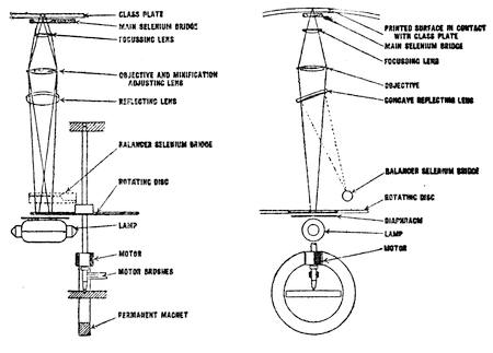
Diagrammatic Arrangement of Optophone.
| FIG. 75.—END VIEW OF THE OPTOPHONE | FIG. 76.—SIDE VIEW OF THE OPTOPHONE |
There is an electric lamp in the machine before which there is a disk that is revolved by a small motor. In this disk there are five circular rows of slots and the light shining through these slots is cut up into five pulsating beams of light. These beams are brought to a focus in a vertical row upon the type page. From the paper they are reflected to a selenium cell or bridge. The selenium bridge forms part of the circuit of a telephone receiver and the diaphragm is thus made to vibrate at the same frequency as the light beams do. By varying the number of slots in each row in the disk the beams of light are given different periods of pulsation or vibration and they produce a sound chord or “scala” in the telephone receiver. The speed of the disk and the disposition of the slots is so chosen that the notes produced are G C′ D′ E′ G′ of the musical scale. Only white paper reflects the light beams; the black surface of the printed type absorbs them. Thus, as the row of beams is swept across a line of printed matter, the beams will be extinguished in various orders of succession, or simultaneously in accordance with the shape of the particular type-character they encounter.
The middle three beams correspond to notes C′, D′ and E′, and play upon the small letters, while G′ plays up the upper part of capital letters, and G upon the tails of such letters as y, p, etc. If the scala passes over the letter “V,” for instance, first the top note G′ is silenced, then E′, D′, C′, D′, E′ and G′ in succession. This arrangement constitutes what is known as the “white sounding” optophone, because the full chord is sounded constantly, except when the type matter is encountered.
To simplify the reading an improved type of optophone has been made, which is known as the “black-reading” optophone, With this machine there is no sound produced except when the type is encountered. The letter “V” is then identified by the sounding, instead of the silencing of the notes G′, E′, D′, C′, E′ and G′. The letter “A” produces the sounds C′, D′, DE′, DG′, DE′, D′ and C′. This result is obtained by using two selenium bridges, as shown better in the side view, Figure 76. There is a concave reflecting lens, which reflects half of the light upon the second cell, known as the balancer selenium bridge. Electric current passing through the balancer opposes the current passing through the main selenium bridge, and hence there is silence in the telephone receiver when the scala passes over plain white paper, but when type is encountered and certain of the beams are not reflected against the main selenium bridge the sounds are produced through the balancer bridge.
The success of the optophone leads one to hope that it may be but the forerunner of a machine that will translate the whole world of light and color into one of music, and permit the blind not only to read by ear, but also to see their friends and their[335] surroundings through the sense of hearing. In fact efforts to make such an apparatus preceded the invention of the optophone.
THE WILLFUL GYROSCOPE
As intimated above, we have included the gyroscope among the higher type of machines, because it seems possessed of a stubborn will of its own, and apparently defies the laws of gravity.
There is nothing mysterious about its mechanism. It is merely a wheel with a heavy rim and with its axis mounted in gimbals, so that it may turn freely in any direction. The wheel, when at rest, behaves no differently from any other mechanism. But once the wheel is set to spinning at a high velocity it seems to acquire marvelous powers and obstinate notions of its own as to what it will do and what it won’t do. You may lift it, or lower it, or move it sideways in any direction, and it will not show the least sign of rebellion so long as the plane of its rotation is not deflected, but attempt to twist its plane of rotation and it will resist with the power of a giant. The resistance that even a small gyroscope will develop is astounding. A wheel weighing not more than 10 pounds may develop so much energy that a man twenty times as heavy pushing with all his might cannot turn it over. Not only does it resist the push, but it actually leans back against the pusher. Then it has the peculiar habit of turning at right angles to the direction in which it is pushed. Suppose, for instance, the axis of the gyroscope is horizontal and it is resting freely on a pair of supports, one at each end. Remove one of the supports and the gyroscope does not fall. To do so it would have to[336] swing around the other point of support as a center; in other words, the plane of rotation would have to be turned angularly and such a motion the gyroscope resists. The unsupported end of the axis dips momentarily under the pull of gravity, but immediately recovers and actually rises above the horizontal, then it begins to revolve slowly in a horizontal circle about the supported end of the axis—a motion which is technically known as “precession”. The pull of gravity exerted in a downward direction results in a horizontal motion at right angles thereto. It seems as if the gyroscope was bidding defiance to laws that govern other objects, but, of course, such is not the case. The gyroscope is as submissively obedient to the laws of gravity as any other object or machine, but the forces which act upon it are so complicated that it is difficult for one to comprehend them without study. In fact, it is almost impossible to explain the strange behavior of a gyroscope without the use of mathematics that is too involved to be presented in this book.
Of course, the underlying cause of gyroscopic action is inertia; i. e., the tendency of a body to retain its state of rest or uniform motion. A bullet is forced out of a gun by the sudden expansion of gases behind it, but after it leaves the muzzle and the influence of the gases, why does it keep on traveling? We may just as well reverse the question and ask why it should ever stop. Having once acquired a certain velocity it keeps that velocity because of its inertia or mechanical helplessness, and it would keep on going forever were it not for the resistance offered by the air and the pull of gravity, which gradually draws it down to earth.[337] It takes a deal of energy to divert the bullet from its course. In a gyroscope we have a similar condition.
FORCES DEVELOPED IN A GYROSCOPE
We may conceive of a gyroscope as consisting of a stream of bullets all tied to a center, so that they fly around in a circle. Any effort to deflect the bullets out of their course will be resisted by each bullet as it comes to the deflector. Here each bullet acts individually, but in a gyroscope wheel the equivalent of the stream of bullets is a solid rim, each particle of which is rigidly connected to every other particle, and so the whole wheel immediately feels the deflecting force and resists it. As long as the wheel is maintained in its own plane of rotation, or moved into parallel planes, there is such a perfect balance of all forces that no more resistance is offered to the motion of the wheel as a whole than would be offered by any other object of equal mass. But when the wheel’s plane of rotation is moved angularly, a complicated series of forces is developed.
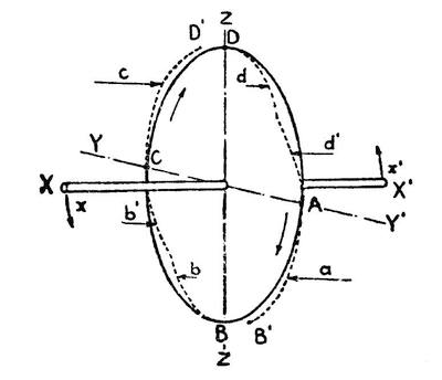
FIG. 77.—SOME OF THE FORCES DEVELOPED IN A GYROSCOPE WHEN ITS PLANE OF ROTATION IS SUBJECTED TO ANGULAR MOTION
Some idea of the nature of these forces and why they give rise to precession may be understood by reference to the diagram, Figure 77. Here we have a disk with a heavy rim turning on the axis X, X′. At A, B, C and D are four particles whose flights we are going to consider. Suppose the wheel to be at rest; then if X, X′ is tilted in the direction of the arrows x x′, the wheel will turn about the line Y Y′; D will move forward toward D′, and B backward toward B′, but A and C will remain where they are. Now, suppose, the wheel to be revolving clockwise, or in the direction A, B, C, D, then the particle A will pursue a spiral course that will bring it to B′, and C will pursue a spiral course that will bring it to D′. However, particle D will have an irregular course, as indicated by the dotted line, starting first to move forward and then curving back toward A. The same will be true of B, except in the reverse direction. The course of particles D and B is, therefore, materially different from that of A and C. Now, the particle D will resist being deflected from its course and will develop an opposing force represented by the arrow d. A moment later this is reversed as the particle bends back toward the axis Y Y′, and we may represent the new force by the arrow d′. It may be proved that the force d′ is more powerful than that of d. The particle A in the meantime exerts a force opposing its deflection, which is represented by the arrow a. On the other half of the wheel there are similar but opposite forces, b, b′ and c. The sum of these forces gives the wheel a tendency to turn about the axis Z Z′. To avoid[339] complicating our diagram with too many arrows, we had better refer to a new diagram (Figure 78) which shows only the resultant of the forces developed. The application of the forces x x′, which would have turned the wheel on the axis Y Y′, had it been stationary, have resulted in the development of forces z z′ at right angles to x x′, tending to turn the wheel about the axis Z Z′. Now, if we go through the same processes of reasoning as before, it will be evident that the forces z z′ will result in a third set of forces y y′ at right angles to z z′ tending to turn the wheel about the axis Y Y′. The forces y y′ exactly balance the forces x x′, and hence the wheel does not turn about the axis Y Y′ in response to the original forces, but starts instead to revolve slowly about the axis Z Z. Because the forces x x′ and y y′ balance each other, there is no fourth couple developed and hence no opposition to the forces z z′.
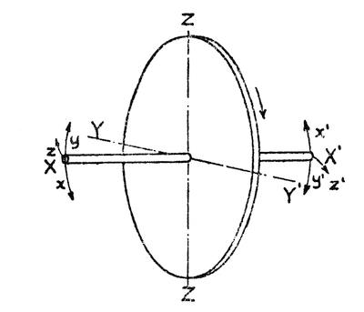
FIG. 78.—DIAGRAM EXPLAINING PRECESSIONAL MOVEMENT OF A GYROSCOPE
The gyroscope was used as a toy ages ago. The top, which is one form of gyroscope, was a favorite plaything of ancient Egypt. But although known[340] these many centuries, it is only in the past few years that any real effort has been made to set the top to work. Because it persists in maintaining its plane of rotation it has proved most useful on submarine torpedoes to control the rudder and hold the torpedo on a true course to its target.
THE GYROSCOPE AS A COMPASS
Another most important use for the gyroscope is found in the submarine itself. The needle of a magnetic compass is kept pointing north by action of the magnetic lines of force which surround this earth. Whenever a large mass of iron is placed near the compass the magnetic field is distorted and the compass needle is deflected from the true north. On modern steel vessels the compass has to be carefully corrected by using iron masses to counterbalance other disturbing masses. However, in a submarine the whole shell of the vessel is of steel and the magnetic lines of force flow along this shell. The compass needle is virtually insulated from the terrestrial magnetism by the surrounding steel hull. But, fortunately, the gyroscope may be used as a compass and it is in no way affected by magnetism. Once the gyroscope is set spinning with its axis pointing to the North Pole of the heavens it will continue to point in that direction no matter how devious a course the vessel may pursue. If pointed in some other direction, the precessional forces set up by the rotation of the earth will turn it due north. As the vessel rolls or pitches, disturbing precessional movements are likely to be set up. These are overcome by special mechanism, so that the gyroscopic compass may now be depended upon as a perfectly reliable instrument.
PREVENTING SHIPS FROM ROLLING
One of the most remarkable recent developments of the gyroscope is its use as a stabilizer in ships to keep them from rolling in a heavy sea. A comparatively small wheel is mounted in the hold of the vessel with perfect freedom to turn in any direction. If the wheel is clamped so that it cannot precess, the vessel will roll and pitch, but the instant the gyroscope is released it exerts its wonderful powers. The ship rides smoothly and its groaning and creaking ceases, showing that it is no longer subjected to severe strains. Of course, it rises and falls with the waves, but it maintains an even keel as if sailing in smooth water. The object of stabilizing a ship is not merely to cater to the comfort of passengers who are subject to seasickness, but to save wear and tear on the vessel and also to economize time and fuel. An unstabilized ship riding a heavy sea pursues a very sinuous course; in other words, it must travel farther than it would in smooth water. The rudder must constantly be turned to keep the ship on its course, and this acts as a drag on the progress of the ship, slowing it down and wasting the power of the engine. As the ship wallows in the sea it displaces much more water than it does when riding on an even keel and here there is a further loss. It has been estimated that a 15,000-ton vessel running at 18 knots may waste as much as 1,000 to 1,200 horsepower in a heavy sea. If stabilized with a gyroscope, practically all this wasted horsepower would be saved at the expense of a very small amount of power used in keeping the gyroscope spinning.
The first man to stabilize a ship with a gyroscope was Dr. Schlick, who demonstrated the powers of this mysterious mechanism in 1906. His stabilizer, however, was not sensitive enough to provide perfect stabilizing. The ship had to roll some before the gyroscope exerted its corrective forces. Recently, however, Mr. Elmer A. Sperry has improved the stabilizer, making it so sensitive that there is practically no rolling or pitching of the vessel.
Curiously enough, the gyroscope may be used not only to keep a ship from rolling, but also to make it roll. Should a vessel run upon a mud flat it may be rocked by braking or accelerating the precessional motion of the gyroscope. In this way the ship may work itself out of the mud bank. Ice breakers are equipped with gyroscopes, so that they may be rolled to prevent them from being frozen into an ice pack and to assist them in crushing their way through the ice.
THE MONO-RAIL CAR
In 1907 a sensation was created by the exhibition of a car which ran on a single rail. The inventor of this monorail car was Mr. Louis Brennan. The public was astonished at the ease with which this car maintained its balance on the rail, leaning in as it rounded a curve to keep its equilibrium. Passengers could move about at will without the slightest danger of upsetting the car; in fact, if a heavy weight was placed on one side of the car that side would rise rather than fall. The car could run with equal ease upon a cable of a crooked pipe line. The gyroscope that maintained the balance of the car consisted of a couple of small wheels which[343] revolved in a vacuum chamber at the rate of 7,000 revolutions per minute. Once started, little power was required to keep them going. Interesting as this car was, it did not offer sufficient advantages over the present-day double rail cars and locomotives to justify its development on a commercial scale. Although witnesses of the exhibition marveled at the strange spectacle of this mechanical tight-rope walker, they did not realize that they themselves had had gyroscopic cars in their midst for years. The gyroscopic action of the wheels of a motorcycle is very marked. It is this action which is mainly responsible for holding the machine upright. The same is true of a bicycle, although the gyroscopic effect is not quite so marked, because of the lower velocity of the wheels. However, we all know that any tendency for the machine to fall to one side or the other may be corrected by a slight turn of the front wheel in that direction which at once has the effect of bringing the bicycle back to vertical position.
THE AUTOMATIC AEROPLANE PILOT
Still another recent development of the gyroscope is its use as an “automatic pilot” on aeroplanes. Two sensitive gyroscopes are used to stabilize the aeroplane. If a gust of wind tends to tilt the machine, the gyroscopes immediately sense the deviation and by closing electrical circuits operate the ailerons to bring the machine back to a horizontal plane.
An aviator possesses a certain sense of balance which is highly developed by experience and long practice, but at its best it does not begin to compare with sense of balance possessed by the gyroscope. Not only will it keep the machine from[344] tipping laterally, but it will also hold it on a level keel and can be used to steer the aeroplane in any desired direction, so that the human pilot may surrender the helm to the faithful mechanical pilot with perfect confidence in the ability of this animated machine to hold the aeroplane on a true course despite the vagaries of the wind. While this is theoretically possible, in practice certain difficulties are encountered which up to the present have prevented gyroscopic control of aeroplanes from being entirely successful.
CHAPTER XXII
HEAT VACUUMS
IN THE preceding chapter we dealt with high temperatures and their employment in melting, molding, and working steel into useful forms. It will be well for us to pause here to consider temperatures at the other end of the thermometer scale, how they are obtained, and the important part they play in modern civilization.
It is not absolutely correct to speak of producing “cold.” We are apt to forget that cold is merely absence of heat. Strictly speaking, there is nothing cold on earth. Everything is more or less hot. A piece of ice at 32 degrees F. is hot compared with a lump of frozen alcohol, and the latter at its freezing point is hot compared with a lump of frozen air, while air at its freezing point is hot compared with a lump of solid helium. In other words, frozen alcohol will be melted by the heat in the ice; frozen air will be melted by the heat in frozen alcohol, and frozen helium will be fused by the heat in frozen air. Everything contains heat, and one object is colder than another only because it contains less heat.
Of course, the temperature of ice may vary. One block of ice may be ten, fifty, or a hundred degrees warmer than another, but ice cannot be heated above 32 degrees F. at the normal pressure of the atmosphere.
Ice is really a partial heat vacuum, a chamber partially exhausted, into which heat will flow if it gets a chance. We pack it away in sawdust, granulated cork, or other materials through which heat can with difficulty penetrate, and then in hot weather cakes of ice are placed in our household refrigerators, so that the heat that is in our food will have something to flow into. When we place our hands near a cake of ice, they feel cool and it seems as if ice radiated cold just as a stove radiates heat; but, of course, such is not the case. The heat of our hands radiates more rapidly in the direction of the cake of ice than in other directions, because there is a partial heat vacuum for the heat to flow into and the result is a sensation of cold.
We no longer depend upon cold winters for our supply of ice. We have learned how to pump heat and we can make heat vacuums, anywhere and at any time, even in the heart of the tropics, and regions in which no natural ice is ever obtainable have the benefits of refrigeration. Furthermore, we are not dependent upon ice for cooling foods. In many cases it is not necessary or even desirable to reduce temperatures to the freezing point of water. A moderate chilling is all that is required for certain foods. By the proper use of refrigerating machinery any degree of temperature may be obtained and maintained. To-day small refrigerating plants are constructed for domestic purposes, so as to render the housewife independent of the ice man.
With refrigerator cars and refrigerating plants on shipboard, fruit from the far west and from tropical lands may be brought to our breakfast[347] table. Meats from northern slaughterhouses may be transported in perfect condition into hot southern climes. There are also certain industries which are dependent on the use of the low temperatures. In breweries, dairies, margarine factories, etc., refrigeration is of the utmost importance, and refrigerating machinery is used for cooling and drying the air blast for blast furnaces.
In some few places refrigerating machinery is used to cool buildings in warm weather and make life more bearable in summer weather. It is highly probable that refrigeration of dwellings will be more and more extensively developed. In winter time we can make the climate in our houses anything we please. Why should we not control the indoor climate in summer time as well?
ABSOLUTE ZERO
The volume of a gas varies inversely in accordance with the pressure to which it is subjected, and also directly according to the temperature. If we start with a gas at the freezing point (32 degrees F.) and reduce its temperature 1 degree (or to 31 degrees F.), we find that the volume of the gas is reduced 1/492.6 of its original volume, provided, of course, that we do not vary the pressure on it. In fact, for every reduction of 1 degree below the freezing point there is a reduction of 1/492.6 of its volume, and for every degree of increased temperature there is an increase of 1/492.6 of the volume. From this it is assumed that at 492.6 degrees below the freezing point, or 460.6 degrees below zero F., we will reach the absolute zero, or the point at which there is no more heat in the gas.
We have not yet succeeded in reaching the extreme of low temperature, although we have come very near it in laboratory experiments. Helium is liquefied at -448 degrees F., which is very near to the absolute zero. At the other end of the scale we have attained enormously high temperatures. The heat of the electric arc, for instance, is between 6,500 and 7,200 degrees F., and that is the highest degree of temperature that we have been able so far to attain.
Human life occupies a very limited zone in this range of temperatures. We must maintain our blood at a temperature of 98 degrees F. A variation of 8 degrees either way is fatal. By piling on heat insulators, such as fur clothing, to retain the heat of our bodies and keep it from flowing out too rapidly, we can maintain the blood temperature at 98 while the surrounding atmosphere may be 70 or 80 degrees below zero. There are internal fires within us that generate heat which radiates from the body, and by checking this radiation by suitable clothing we can maintain our blood at the normal temperature.
But what can we do when the surrounding temperature is higher than blood heat? The outside heat may be kept from flowing in by surrounding ourselves with heat-insulating clothing, but the internal heat then has no means of radiating away from our bodies; it accumulates, and we become overheated. However, Nature provides a cooling system in the perspiration which oozes from our pores, and as this evaporates it cools the skin and enables us to maintain our normal blood heat, although submerged in an atmosphere of a higher temperature. If the air is dry, the evaporation is[349] more rapid and the cooling is greater than in a moist atmosphere. That is why a temperature of 105 degrees on our Western plains may be more endurable than a temperature of 95 degrees in the moist atmosphere of New York. The importance of keeping down the temperature of the blood is particularly appreciated by physicians, and for this reason the earliest attempts at artificial cooling were made by physicians.
EARLY USES OF LOW TEMPERATURES
Very early in his history man discovered fire, learned how to kindle it and how to use it for his good. That discovery placed him immediately on a level far above the beasts. However, it is only in comparatively recent times that he has learned the uses of low temperatures. Nature’s stores of ice were drawn upon, and methods of preserving ice through warm weather were discovered in ancient times. Nero had ice houses built for him in Rome, but he could stock these buildings only with the ice that nature furnished him. Freezing mixtures of salt and ice, such as we use in our ice-cream freezers to-day to obtain temperatures far below the freezing point of water, were probably known in early times, but the ancients did not know how to produce ice.
Artificial ice was probably first made in India, where it has long been the practice to produce ice by evaporation. Water is placed in shallow pans and then dry air is circulated over it, causing so rapid a vaporization as to cool the water to the freezing point. The idea of cooling water by evaporation belongs to very ancient times. Water placed in porous earthen vessels was found to be[350] cooler than water kept in water-tight jars. The moisture that escaped through the vessel would evaporate, and in so doing draw heat out of the vessel and its contents. To-day campers keep water cool by putting it in canvas buckets and hanging the buckets in the wind, so that the moisture oozing through the canvas will evaporate quickly.
It was not until 1755 that a mechanical means of producing low temperatures was developed. The inventor was Dr. Cullen, and he used an evaporation system, expediting the evaporation by producing a partial vacuum over the water. But nearly a century elapsed before the first commercially successful refrigerating machine was built. Even then the advantages of artificial refrigeration were not fully realized, and it was not until late in the last century that real progress was made. Since then the development of artificial refrigeration has been truly remarkable.
HEAT AND MECHANICAL ENERGY
There is a definite relation between heat and mechanical energy, in fact the two are mutually convertible. The amount of heat required to raise the temperature of a pound of water 1 degree F. is called a British thermal unit or a B. t. u. This measure is taken at 39.1 degrees F., because at that temperature water is at its densest. Since heat and mechanical energy are mutually convertible, we can express foot-pounds or horsepower in B. t. u. One B. t. u. is equivalent to 778 foot-pounds of energy. In other words, the amount of heat that would raise the temperature of a pound of water 1 degree F. would, if converted into mechanical[351] energy, be sufficient to raise a weight of 778 pounds to a height of one foot, or one pound to a height of 778 feet. A horsepower is equivalent to 2,545 B. t. u. per hour.
Heat from burning coal is used to generate steam, and this in turn is used to operate a steam engine and thus heat is converted into mechanical energy (unfortunately most of the original heat units in the coal are wasted, as was pointed out in a previous chapter); but heat will not flow from one body into another of higher temperature without the expenditure of mechanical energy. It always flows from a hot body into a cold one, and not from the cold body into the hot one, unless it is actually pumped up to the higher heat level by some mechanical means. A refrigerating machine is actually a heat pump with which we produce a partial heat vacuum.
Whenever a gas is compressed, heat is generated. Anyone who has operated a tire pump knows how hot the pump becomes from the heat that is seemingly squeezed out of the compressed air. As was noted in Chapter VIII, heat is liable to give trouble in an air compressor, and sometimes the temperature rises to such a point that there is an explosion of the air and the vapors coming from the oil used to lubricate the machine. The compressed air is therefore cooled by means of water jackets or coils of pipe through which water is passed. In this way the excess heat is carried off. When, however, cooled compressed air is relieved of pressure and allowed to expand again the process is reversed. A partial heat vacuum is formed and heat from surrounding objects flows into the vacuum. In other words, the surrounding objects are cooled.
COLD AIR MACHINES
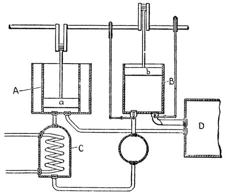
FIG. 79.—COLD AIR MACHINE
It is a simple matter to make a machine which will alternately compress, cool, and expand air in such a way as to produce a lowered temperature. Such a machine is indicated diagrammatically in Figure 79. There are two cylinders, A and B, and a condenser at C. When the piston a in cylinder A descends it compresses the air in the cylinder; this air flows into the condenser C. There is a coil of pipe in this condenser through which water circulates. This carries off the heat of compression and then a valve is opened which permits the cooler air to pass off into cylinder B. As the air expands in this cylinder it becomes chilled. This chilled air is then forced out of cylinder B by means of piston b and flows into the refrigerator or cold storage room D. As the air is liable to take up moisture and to introduce objectionable vapors from oil used to lubricate the pumps, it is usually confined in pipes in the refrigerator and then returned to the cylinder A.
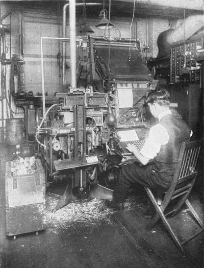
COMPOSITOR AT WORK ON A LINOTYPE MACHINE
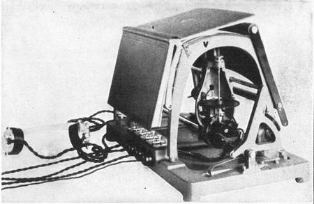
THE OPTOPHONE
An instrument which enables the blind to read common print
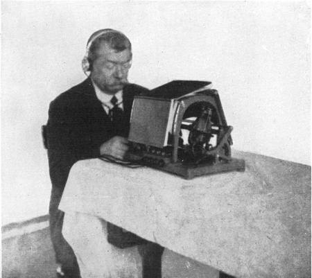
A BLIND MAN READING WITH HIS EARS
This is a type of a refrigerating machine that is used very extensively on ships for chilling perishable foods. However, air has only a very low capacity for heat, and in order to obtain an appreciable amount of refrigeration very large volumes of air must be handled. This means that cold-air machines must be very large and bulky. The efficiency of such machines is low, but they find favor on shipboard because there are no inflammable or poisonous gases to be dealt with. In the standard machine of the United States Navy air is compressed to 260 pounds; and in the expansion is raised to 60 pounds pressure, which is enough to reduce the temperature to between 70 to 90 degrees below zero.
LATENT HEAT
Far more efficient are the machines which utilize latent heat. As explained in a previous chapter, whenever a solid is converted into a liquid or into a gas a certain amount of heat is absorbed and stored up in such a way as not to become apparent to the senses or to a thermometer. Such heat is known as “latent heat.” For instance, we can add a pound of water at 50 degrees temperature to a pound of water at 200 degrees, and the mixture will have a temperature of 125 degrees, or the mean of 200 + 50 degrees. But a pound of ice at 32 degrees mixed with a pound of water at 200 degrees will not give us 116 degrees ((200+32)/2), but only 44½ degrees. In other words, about 143 heat units will[354] be rendered latent in converting solid water into liquid water, reducing the temperature of the water to 57 degrees and then the mean of 57 and 32 is 44.5 (200-143=57, (57+32)/2 = 44½). A more striking experiment is to mix a pound of water cooled to 32 degrees F. with a pound of water at 175 degrees F., and the result will be two pounds of water at 103.5 degrees, but if we mix a pound of chopped ice at 32 degrees F. with a pound of water at 175 degrees F., the result will be two pounds of water cooled to the freezing point.
In passing from a liquid into a gas water absorbs far more heat and renders it latent. For each pound of water converted into steam at atmospheric pressure 970 B. t. u. are absorbed. This storage of latent heat is utilized to good advantage in refrigerating machinery. The vacuum machine invented by Dr. Cullen in 1755 was a latent heat machine.
VACUUM MACHINES
As we have observed before, the boiling point of a liquid depends upon the pressure to which it is subjected. Under the normal atmospheric pressure of 14.7 pounds per inch the boiling point of water is 212 degrees F., but if the pressure be increased the boiling point rises, and if it be reduced the boiling point is lowered. In a partial vacuum of ten pounds absolute pressure the boiling point is 193.2 degrees, at one pound it is 102.1 degrees, and if the pressure is reduced to .089 pound water will boil at 32 degrees, or its normal freezing point. Dr. Cullen, by exhausting the air from a vessel containing water, made the water boil or vaporize at a low temperature. In order to boil it had to[355] absorb heat, and not being supplied with any external heat it had to draw upon itself, thus producing ice.
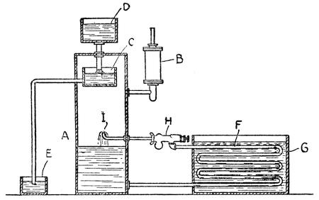
FIG. 80.—DIAGRAMMATIC VIEW OF A VACUUM REFRIGERATING MACHINE
Dr. Cullen’s machine has been improved upon by using various chemical substances to absorb the water vapor. Such a machine is shown in Figure 80. The vacuum chamber A is partly filled with brine, which may be cooled below the freezing point of pure water without congealing. A pump, B, maintains a vacuum in the chamber. In the upper part of the vacuum chamber there is a vessel, C, into which sulphuric acid is sprayed from a reservoir, D. This acid has a strong affinity for water vapor and hastens the evaporation by absorbing the vapor with which it comes in contact. The mixed sulphuric acid and water flows over into a receiver, E. The acid is reconcentrated by steam heat so that it can be used over again. However, this feature of the process is not shown in the diagram.[356] Brine from the chamber A passes through a coil of pipe F in the tank G, where the ice is made, and it is returned to the vacuum chamber by an injector H, which at the same time introduces fresh water into the chamber to take the place of that absorbed by the acid. The fresh water and brine enter as a spray at I, so as to increase the rate of evaporation.
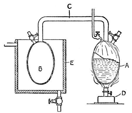
FIG. 81.—ORIGINAL ABSORPTION MACHINE
THE ABSORPTION PROCESS
Another form of refrigeration is known as the absorption system, and strangely enough direct heat is applied to the machine in one place in order to abstract heat from it in another. A diagrammatic representation of the first machine of this type (which was invented by Frederick Carré) is shown in Figure 81. Two vessels, A and B, are employed,[357] which are connected by a tube C. The vessel A contains ammonia solution. A lamp, D, is placed under the vessel A. Sufficient heat is produced to vaporize the ammonia, whose boiling point is very low, and distill it out of the water in the solution. It passes through tube C into vessel B. This vessel is surrounded by a tank, E, containing cold water, which condenses the ammonia vapor into liquid ammonia, then the process is reversed.
The circulation of water through tank E is checked and water from pipe F is sprayed on vessel A. This cools the contents of vessel A, producing a partial vacuum. The ammonia in chamber B boils and its vapors pass back into chamber A, where they are reabsorbed by the water in that chamber. The rapid vaporization in chamber B absorbs heat from the immediate surroundings and will freeze water placed in the tank E.
In commercial practice the absorption system is very extensively employed. The ammonia is placed in a large cylinder known as a generator and is heated by steam coils. The ammonia vapor passes through an analyzer which traps any water vapor it may contain, and then it goes through a series of condensing coils, which are cooled by water. In these condensing coils the ammonia vapor is liquefied by the pressure in the generator and collects in a receiver, whence it passes through an expansion valve into the cooling coils in the brine tank. From the cooling coils the ammonia gas passes back through an absorber which reverses the operation of the generator. Here weak aqua ammonia is sprayed on the ammonia gas and absorbs it. The rich ammonia solution is then pumped into the generator.
There are several auxiliary apparatus which are omitted in this brief description in the interest of clarity.
THE COMPRESSION SYSTEM
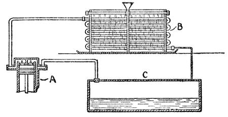
FIG. 82.—DIAGRAMMATIC VIEW OF A COMPRESSION MACHINE
One more type of refrigerating machine remains to be described and that is the compression type. This was invented by Jacob Perkins in 1834, but was not developed into a commercial machine until 1850. This machine is the most important of them all. In some respects it is like the absorption process, but in place of adding direct heat a compressing machine is employed. Figure 82 illustrates the system diagrammatically. At A is the compressor which compresses ammonia gas. The gas which is heated by the compressor is then cooled and liquefied in the condenser B. Thence it passes into a brine tank C, where it expands and absorbs heat. From this point it is drawn back into the compressor, thus completing the cycle. In other words, the ammonia must absorb as much heat from the brine as is taken out of it at the condenser.
CHAPTER XXIII
ENGINES OF DESTRUCTION
AT THE VERY beginning of this book we observed that war is a most potent stimulus to invention among primitive men. Despite all our advances in civilization we still have our wars, each more dreadful than the preceding one; for each important conflict brings forth new engines of destruction or stimulates the invention of new death-dealing machines which are developed during intervals of peace. So terrible has modern war become that with each great conflict it has seemed as if its very dreadfulness would stay the hand of the invader and make him hesitate to expose his men to the horrible monsters which science and invention have created. To-day, after a titanic struggle which cost millions of human lives, which destroyed billions of dollars’ worth of property, and which made itself felt to the remotest corners of the earth, serious efforts are being made to banish war, but at the same time inventors here and abroad are busy inventing new and more powerful engines of death, and the prospects are that the next big war, should there ever be one, will be even more horrible and destructive than the one we have just passed through.
Fortunately engines of death are not the only inventions produced by war. Many machines, apparatus, and processes are originated or developed which have a distinct value in time of peace; hence[360] war is a great constructive as well as a destructive agency. In this respect the great World War was no exception and we are already reaping benefits which in a small way compensate for the havoc that was wrought. It advanced scientific research to a point it would not have reached in fifty years of peace. The stimulus was felt in every field of science from chemistry to acoustics, from geology to meteorology. Wonderful progress was made in radiotelephony, in submarine navigation, in aviation, and there were scores of inventions which will add to our comfort and aid us in the mastery of Nature.
Many of these inventions have already been described; others do not properly belong in this volume as they have to do chiefly with electricity or chemistry. In this chapter we shall take up mainly the machines built for the purpose of destroying men and their works.
PRIMITIVE “ENGINES” OF WAR
Of course the main objects of war are offense and defense, the destruction of the opponent and the protection of one’s self. This first fighting was a hand-to-hand struggle which gave way to fighting at a distance as spears and arrows were invented. Shields and armor were then invented to ward off these missiles. Cities were surrounded with walls to hold off the enemy. Then came the Roman war “engines,” catapults and battering rams, to destroy the walls and towers which would enable the besiegers to fight on an equal level and in personal contact with the besieged. Although a battle might start with long-distance fighting it was always a hand-to-hand encounter that clinched the victory. Even to-day, although we have our big guns which[361] fight at ranges of five to twenty miles, it is the rifle or bayonet which wins or loses the battle.
INVENTION OF GUNPOWDER
The introduction of gunpowder from China in the fifteenth century did not immediately revolutionize warfare. It was used only in cannon or mortars for hurling large stones at city walls. The range of those cannon was so limited and the time it took to load and fire them was so great that they were of little use on an open battlefield. A cannon, although a comparatively powerful offensive weapon, was helpless against attack and was only suitable for use in forts or behind breastworks. Later when its range was increased and it came to be used on the battlefield it had to be protected from capture by men supplied with small arms.
This defect of the cannon also applied to the use of the hand gun. Its range was small and consequently the blunderbuss type was invented to spread the charge of shot as much as possible so as to tear a wide gap in the enemy’s line and prevent it from closing in upon the operator of the gun. But the loading and firing of these early firearms was extremely slow and the battle-ax and even the arrow and the crossbow were much more effective weapons. So unreliable were the muskets of our Revolutionary War that in battle more dependence was placed upon the bayonet than the firearm.
THE SPINNING BULLET
Three important improvements were necessary to make the small gun a really effective weapon. First was the invention of a reliable means of igniting the powder; second the rifling of the barrel so that[362] the bullet would not tumble but would hold a true course, and finally the invention of a cartridge and a rifle that could be loaded from the breech. These improvements were not completely effected until the time of the Civil War. Since then there have been further marked improvements: The power of cartridges has been increased; the bullets have been given a stream-line form so as to increase the range of the rifle and its power of penetration; the rifle has been equipped with a magazine for carrying a number of cartridges; and a simple mechanism has been provided for discharging empty shells and inserting fresh cartridges in a minimum of time.
Gyroscopic action plays a very important part in the flight of a bullet or shell. The spiral grooves cut in the bore of the rifle give the projectile a twist that sets it to spinning rapidly. The spinning bullet is virtually a gyroscope and maintains its axis in the line of flight. Hence it is possible to use a long pointed bullet instead of the round ball of earlier days and to give the projectile a shape that will enable it to cut through the air with comparatively little resistance. The same bullet fired from a smooth bore gun would begin to tumble and would encounter so much air resistance that it would fall short in the space of a few hundred feet, besides which it would wander far off its course.
MACHINE GUNS
A rifle is really a machine for hurling small projectiles. During the Civil War a Chicago physician named Gatling fell to pondering over the inefficiency of using a machine that would fire only one bullet at a time with a considerable interval of time between shots for reloading, and he hit upon the idea[363] of developing a machine that would discharge a continuous stream of bullets. So he built a ten-barrel revolving gun operated by a hand crank. The barrels were automatically loaded and fired one after the other. Although it was slow to accept the Gatling machine gun, the U. S. Army after once accepting it was loath to give it up even after better machine guns were invented.
UTILIZING THE KICK OF A GUN
In the Gatling gun hand power was required to operate the loading, firing and shell-ejecting mechanism, but it occurred to another inventor that a small portion of the energy developed in exploding the cartridge could very well be utilized to replace the hand power and thus make the machine gun completely automatic. It was Hiram Maxim who first carried out this idea to a successful conclusion. When a rifle is fired the suddenly expanding gases push back against the breech of the gun with just as much pressure as they do against the bullet and this shows itself in the recoil or “kick” of the gun. Maxim utilized the kick of the gun to cock the gun, open the breech, eject the empty shell, take a fresh cartridge out of a magazine belt, insert it in the breech chamber, lock the breech and fire the gun. All these operations occupied but an instant of time and the gun kept on firing as long as the belt of cartridges held out.
John M. Browning, inventor of the Colt gun, instead of using the recoil, employed a small portion of the gases to operate the mechanism. A minute hole in the barrel of the gun, near the muzzle, communicated with a small cylinder in which was a spring-pressed piston. The gases pursuing the[364] bullet out of the barrel would find this tiny hole and, entering it, push back the piston. The pressure against the piston would be only a small fraction of that exerted against the bullet and would last for only the briefest part of a second, from the time the bullet uncovered the hole to the time it emerged from the barrel and liberated the gases, but this minute portion of the energy of the powder was sufficient to actuate the mechanism which performed all the operations necessary to reload and fire the gun.
COOLING THE GUN BARREL
The advantage of these machine guns over Gatling’s lay not only in the saving of human labor, but in the fact that a single barrel was employed in place of ten, thereby greatly reducing the weight of the gun. But a serious handicap was encountered in the heat developed by the burning powder. Dr. Gatling, by using ten barrels, could let nine be cooling while the tenth was discharging, but even he found it necessary to place a water jacket about half the length of the barrels. In the Maxim machine gun a large water jacket enveloped the whole length of the barrel and when the gun was firing continuously at a moderate rate the 7½ pints of water contained in the water jacket would come to a boil inside of a minute and a half, and thereafter more than a pint would be evaporated each minute of firing, or about a pint and a half per thousand rounds. The necessity of using water-cooling added considerably to the weight of the gun and made it occupy in the service an intermediate place between the shoulder rifle and the big gun.
Another method of cooling was to use a barrel with a large outer diameter and depend upon the[365] radiation of heat from the outer surface to prevent overheating. This was later improved by putting flanges on the outer surface of the barrel, so as to increase the radiating surface, in the same way that the cylinders of a motorcycle are kept cool. The barrel was made easily detachable and a spare one provided, so that as soon as the barrel grew excessively hot it could be removed and replaced with a cool barrel. The fault of overheating is not that it might explode the cartridge prematurely but that the bore will be enlarged by heat expansion so that the bullets will not take the rifling and will come out of the barrel as if from a smooth-bore gun. In a test of a Hotchkiss machine gun which was fired continuously the expansion was sufficient at the end of four minutes to make the course of the bullets very uncertain and in seven minutes the bullets, emerging without any spin, tumbled over and over and failed to carry more than three hundred yards.
A GUN THAT FANS ITSELF
The next marked step in the development of the machine gun was to make it fan itself and thus keep its barrel cool. Col. I. N. Lewis designed a gun operated by gas pressure somewhat on the principle of the Colt gun and around the barrel he fitted sixteen deep flanges or fins of aluminum that ran lengthwise of the gun. Around these fins he fitted a casing, thus forming 16 long narrow chambers about the barrel. The casing was open at the breech end, but at the outer end was contracted into a narrow mouthpiece that extended beyond the muzzle. The mouthpiece was so formed that as the bullets passed through it they sucked air through the chambers, thereby cooling the gun. The air travels[366] through the casing at the rate of about seventy miles per hour.
This design permitted Col. Lewis to build a very light gun. Its total weight was but 25½ pounds and it could be handled by a single man if the muzzle was supported on some sort of a rest. It represented a marked step toward a shoulder machine gun which would increase enormously the efficiency of infantry equipped with this weapon. The difference between rifle fire and machine-gun fire has been likened to the difference between trying to hit a tin can with a stone and with a stream of water from a hose. In the latter case the hose may be raised or lowered to correct the course of the stream and bring it to bear on the target. In the same way by watching the effect of the machine-gun bullets the leaden stream may be corrected to bring it directly upon the target. The advantages of a weapon such as this, which may be fired from the shoulder or from the hip, are perfectly obvious.
As the war was nearing its end John M. Browning produced two machine guns, one a water-cooled heavy model fired from a stand. The total weight of this gun was 34½ pounds and with the water jacket empty it weighed but 22½ pounds. It was operated by the recoil of the gun, but the mechanism was greatly simplified and there were but few parts. These could be taken apart and replaced with new ones in a minimum of time in case of breakage. The other gun was a shoulder rifle weighing only 16 pounds, which carried a clip of twenty cartridges. These could be fired singly or in rapid succession in the space of two and a half seconds. Only a second was required to replace the empty clip with a filled one. No special cooling apparatus was provided[367] because it was not likely that a shoulder rifle would be fired long enough at a time to become excessively heated.
POCKET-SIZED MACHINE GUN
The latest development in machine guns is a pocket edition weapon—a firearm weighing only 7 pounds and measuring but 22 inches over all. This little gun which is too small to be classed as a rifle and yet rather large for a pistol, has two grips so that it may be fired from the waist line, and it may be fitted with a gun butt so that it may be fired from the shoulder. It operates at the astounding rate of 1,500 shots per minute or three times the speed of the average machine gun. The cartridges are fed either from a box magazine containing 20 rounds or from a drum-shaped magazine loaded with 50 to 100 cartridges. The operating mechanism of this gun is entirely different from anything produced heretofore and depends upon a discovery made by Commander Blish of the United States Navy. He found that a wedge of a certain angle will hold a breechblock closed against the pressure of an exploding cartridge while the pressure is high, but will slide when the pressure falls. Apparently at first the adhesion due to friction is too great to permit the wedge to move, but the adhesion falls off more rapidly than the pressure does and a point is reached at which the wedge yields to the pressure. In the “submachine” gun, as the new weapon is called, the barrel (or rather an extension of the barrel) and the receiver, in which the operating mechanism is contained, are locked together by a wedge. The wedge slides in slots set at an angle of 80 degrees with the axis of the barrel. When a cartridge[368] is fired the wedge remains fast while the bullet is traveling through the bore, but when it emerges and the pressure of the gases falls off the wedge slides, unlocking the breech mechanism. The gun is remarkable for its simplicity and the fewness of its parts. It has been adopted by the Police Department of New York City.
ARTILLERY VS. ARMOR
As has been stated above, gunpowder was first introduced in warfare not for the purpose of destroying men, but for smashing city walls and fortifications, so that infantry could pour through the breeches made by the heavy stone or iron projectiles. As artillery grew more powerful and the aim more accurate walls of masonry gave way to earthworks and to masses of concrete and armored steel. However the World War demonstrated the impossibility of building any fortifications above ground that would stand up against modern high-powered guns.
GUNS, MORTARS, AND HOWITZERS
In military parlance a “gun” is a long-barreled piece that fires its projectiles with a flat trajectory, that is, the projectile is fired at a low angle and describes a long flat curve. A “mortar” is a short-ranged weapon which fires at a high angle so as to land its projectile over the walls of a fortification. The barrel of the mortar was formerly very short and had a smooth bore, but later the barrel was extended and the bore rifled so as to give a greater range, developing what is known as the “howitzer.” The famous 42-centimeter gun with which the Germans started the war was a howitzer which fired a shell a yard and a half long weighing 2,108 pounds.[369] We have big guns to defend our coasts which fire a shell 16 inches in diameter, which is half an inch less than 42 centimeters, and the weight of the shell is 2,400 pounds. But the startling thing about the German big howitzers was that they were portable and could be brought up to smash fixed defenses. As the war proceeded enormous guns as well as howitzers were set on railroad mounts and moved about from time to time to avoid discovery by spying aviators.
THE 76-MILE GUN
The 76-mile gun which bombarded Paris fired projectiles of only 8.27-inch caliber. The projectile described a wide curve which carried it about twenty-four miles above the surface of the earth or about 3½ times as high as the greatest altitude ever reached by man in an aeroplane. Had it pursued a perfectly straight line from the forest of St. Gobain to Paris its course would have carried it 3,750 feet below the surface, because of the curvature of the earth. The range of the projectile was very materially increased by rising to such a great elevation because of the extreme tenuity of the atmosphere. The air resistance that a shell is obliged to overcome is not generally appreciated. In the denser strata of the lower atmosphere the resistance is very great, but as a shell mounts to higher levels the air resistance falls off considerably and at twenty miles it is practically nonexistent.
It was not until the summer after the armistice that details of this gun were disclosed. There were seven of these powerful guns that participated in the various bombardments. They wore out very quickly under the terrific strain to which they were subjected and were rebored to a diameter of 9.4[370] inches. In the last bombardment a number of shells of this size reached Paris. The guns were fired at an angle of 55 degrees from the horizontal so as to pass quickly through the denser layers of the air. The shell left the muzzle of the gun with the velocity of about 5,000 feet per second and arrived in Paris about three minutes later with a velocity of about half that amount. The enormous muzzle velocity was obtained by using a very long gun so that the powder could keep pushing the projectile for a comparatively long time. The guns were built out of worn-out 15-inch naval guns. These guns which were 56 feet long were rebored, fitted with a heavy tube and pieced out to a length of 118 feet. The last 20 feet of the bore was not rifled and served as a guide to keep the shell in perfect axial alignment when it emerged from the muzzle. A comparatively slow powder was used so as not to put too severe a strain on the gun at the breech, but gradually to accelerate the shell in its travel through the bore.
Spectacular as was the performance of these huge guns, they were of little military value. The slightest variation in the powder would cause a wide variation of range and they could not hope to hit a target smaller than a large city. All seven guns fired a total of 303 shells in 44 days of bombardment, only 183 of which fell within the city. They killed 256 persons and wounded 620. Far more damage at far less expense could have been effected by dropping bombs from aircraft.
A 121-MILE GUN
Just as a problem in ordnance, American officers designed a gun 225 feet long which would fire a 400-pound shell of 10-inch caliber. It was estimated that with a charge of 1,440 pounds of[371] powder the shell would leave the muzzle with a velocity of 8,500 feet per second and, if fired at an angle of 55 degrees, would have a range of 121 miles. The shell would rise to a height of 46 miles above the earth and would make the 121 miles in about 4 minutes. The gun was never built, because its military value would in no way be commensurate with its cost of construction and operation. The purpose of the German long-range bombardment was to produce a moral rather than a military effect. The Germans hoped to intimidate the French people by this spectacular performance, and in this they failed completely.
TIMED AND PERCUSSION SHELLS
In modern warfare large guns are used either to rain a storm of death upon infantry or to destroy their defensive works. In earlier days the effectiveness of gunfire against a charging enemy was increased by the use of grapeshot. A cannon was thus converted into a gigantic shotgun. But although a wide dispersion of projectiles was obtained the range was very limited. This handicap was then overcome by having the gun fire another gun which would discharge when it had reached the enemy’s lines. In other words, the grapeshot or leaden balls were packed into a shell which was fired like a solid projectile, and this exploded when it struck the target, scattering death broadcast. An improvement on this was the timed shell, which would explode while still in the air and scatter its rain of lead over a wide area. The time fuse of a shrapnel shell must be very delicately adjusted to explode at the desired instant. A train of powder is used which may be short-circuited to give the[372] exact length required for any given distance. The powder is ignited by a cap which is exploded by concussion when the gun is fired. The fuse then burns until it reaches the main charge of the shell. This explodes, bursting the shell open and scattering shell fragments as well as the scores of lead balls with which the shell is packed. Should the fuse fail, a detonating pin is provided which will explode the shell when it reaches the ground. Where the object is to destroy defensive works the shell is charged with a high explosive which is detonated not by a time fuse, but by concussion when the shell strikes its target.
The war brought forth many new types of projectiles: shells loaded with lethal gases; shells which left a trail of smoke whereby their course could be followed when fired at aircraft; shells that illuminated the battlefield at night, etc. The searchlight shells carried a number of “candles,” each furnished with a little parachute so that when the shell exploded the burning candles would settle slowly to the ground, all the while casting a brilliant light on operations below.
AERIAL BOMBS
Obviously, hurling projectiles from the air is a much simpler matter than projecting them from the ground. No propellant is required to carry them to the target and no rifling is necessary to keep them head-on in the direction of flight. They are pulled instead of being pushed and can easily be kept in their course by means of rudder planes. But hitting a target from an aeroplane is like hitting a swiftly moving object from the ground. The target is seemingly flying past the aeroplane and in calculating where the aerial bomb will strike the[373] speed of the plane through the air and its height above the ground must all be taken into consideration.
Naval warfare is a fight of fort against fort and consequently the high explosive projectile is the principal one used. The shells must be able to penetrate heavy steel armor and explode within the hull of the vessel. In addition to these we have the torpedoes fired by destroyers and submarines which explode an enormous quantity of high explosive against the hull of the vessel. No attempt is made to penetrate the skin of the vessel, but the explosive, tamped by a considerable depth of water, delivers a very heavy crushing blow against the side of the hull.
AUTOMATIC CONTROL OF SUBMARINE TORPEDOES
It is wrong to speak of firing a torpedo. A torpedo is really an automatic, self-propelled, submarine boat. All that the destroyer or submarine does is to set the steering gear in this little boat and then launch it at the enemy with a blast of air that ejects it from the torpedo tube. Most of the body of the torpedo is filled with compressed air which drives a small air motor coupled to a pair of propellers. These propellers run in opposite directions so as to balance each other and they drive the torpedo through the water at a speed of about forty miles per hour. The speed falls off gradually as the air supply is exhausted.
To hold the torpedo on its course horizontal and vertical rudders are employed. The vertical rudder is controlled by a gyroscope which turns it this way or that according as the torpedo tends to veer off its course.
The value of a torpedo lies in its concealment. Were it to travel on the surface the vessel against which it was directed might be able to avoid it; furthermore the action of the waves would tend to disturb the gyroscopic steering mechanism and the torpedo would pursue an erratic course. For this reason it must travel under water at a depth sufficient to avoid surface disturbances. There is also a distinct advantage in having a good cover of water over the torpedo when it strikes its target because the force of the explosion, although felt in all directions, is mainly expended along the line of the least resistance. If the depth of water over the torpedo is slight, most of the force will be expended upward and only a comparatively small part will act against the hull of the vessel. It was the practice of the Germans to set their torpedoes for a depth of about ten feet.
To hold a torpedo at a fixed depth a very delicate hydrostatic valve is employed which operates the diving rudders. The valve is set for a certain depth or weight of water. If the torpedo goes below this depth, the weight of the water bearing on this valve presses it down and thereby tilts the diving rudders until the torpedo comes back to the required depth. If it rises above the depth for which it is set, the valve feels the reduction of water pressure and tilts the rudders in the opposite direction to correct the deviation from the predetermined line of travel. Once the valve has been set the torpedo takes care of itself automatically. It may be discharged from any depth or be dropped from torpedo tubes on the deck of a ship and after a few undulations it will find its depth and hold it as long as it keeps running.
Torpedoes have actually been discharged from aeroplanes and it is possible that in the next great war swiftly flying aeroplanes may actually bring death and destruction to powerful dreadnoughts. In fact winged destroyers and battle cruisers of the air may render obsolete all our modern fighting machines.
As we have already observed, it was war that first aroused the inventive instincts in man. Fortunately this instinct was not confined to destructive devices and engines, and the mechanical conquest of the earth, although it continues to derive much benefit from the stimulus of war, may well afford to break off relations with so grim and horrible a partner and proceed to develop under the stimulus of its own successes.
CHAPTER XXIV
SUMMARY OF MECHANICAL PROGRESS
THE REAL beginning of the present age of machinery dates from Watt’s invention of the double-acting steam engine which was patented in 1782. Prior to that date the steam engine was used merely for pumping water, but now in its new form it was adapted for use in driving industrial machinery. But, as we have shown in another chapter, it was not until John Wilkinson invented his boring machine in 1774 that it was possible to bore the cylinders that Watt used in his engine.
In the field of machine tools there were several notable inventions. Henry Maudslay invented the slide rest for lathes and later in 1797 the screwcutting lathe. Joseph Bramah invented the hydraulic press and Maudslay furnished the cup leather packing that made it a success. Woodworking machinery, and particularly mortising machines for making pulley blocks, were invented by Samuel Bentham and patented in 1791 and 1793.
In the textile industry we find the spinning jenny invented by Hargreaves in 1770, Richard Arkwright’s roll-drawing spinning machine invented in 1769 and 1775, and Crompton’s mule spinner invented between 1774 and 1779, but never patented. In addition to this there was the invention of the cotton gin in 1794 by our own Eli Whitney and Dr. Cartwright’s series of patents on the power-driven[377] loom granted between 1785 and 1788. In 1799 Louis Roberts invented a machine that would make a continuous web of paper. The machine was developed in England by the Fourdrinier Brothers and has ever since borne their name.
1801-1810
Just before the Nineteenth Century dawned the patents on Watt’s steam engine expired and the invention became public property.
Trevithic applied steam power to the propulsion of a coach in 1801. This was the forerunner of the automobile and it led to the invention of the first steam railway and locomotive three years later. Steam was also applied to the propulsion of boats in this decade and reached the practical stage when Fulton built the Clermont in 1807. The first application of steam to the driving of a loom is accredited to William Horrocks in 1803. Jacquard’s loom attachment for producing various patterns was invented in 1801. The first knitting machine in which the latch needle was used was patented in France in 1806 by Jeandeau.
Among the machine-tool developments the most important were Bramah’s invention of the planer in 1802 and Brunel’s mortising machine in 1801. A process of making malleable iron castings was invented by Lucas in 1804. The percussion lock for guns was invented by Forsyth in 1807.
1811-1820
The second decade saw a much wider application of steam and considerable development in locomotives. Hedley’s “Puffing Billy” was built in 1813, and Stephenson’s first locomotive in 1814.
In the same year Fulton built the first steam war vessel and five years later the Atlantic was crossed for the first time by a steamer, the Savannah. The rotary steam printing press belongs to this decade.
The circular knitting machine was invented by Brunel in 1816. About 1818 Eli Whitney invented the milling machine, and in 1819 Blanchard invented his “gun-stocking” lathe with which irregular forms could be turned out. The breech-loading musket was patented in this country by Thornton and Hall in 1811.
1821-1830
In this decade we find the conversion of electricity into mechanical motion and many other important electrical developments, which, however, are omitted from this list as we are confining ourselves to mechanical inventions. There were marked developments in steam railroads. Stephenson built the “Rocket” which won prizes on the Liverpool and Manchester Railway, and the first locomotive was imported into this country in 1829. The tubular locomotive boiler was invented by Seguin in 1828 and Ericsson’s portable steam fire engine was built in 1830. In the previous year an important improvement in spinning mules was made when John Thorpe invented the ring frame.
1831-1840
Important railroad developments mark the opening of this decade. The famous locomotive “John Bull” was imported from England in 1831 to operate on the Camden and Amboy Railroad. The following year saw the first American-built locomotive, “Old Ironsides,” which was built at Philadelphia by[379] the Baldwin Locomotive Works. Stephenson’s link motion, also claimed by W. T. James, was invented in 1832.
However, the most important development of the decade was the invention of the reaper. Hussey’s patent was obtained in 1833 and McCormick’s the following year.
Colt’s revolver (1836); Perkin’s portable ice machine (1834); Anthony’s (1831), Tolle’s (1834), and Burden’s (1835) developments in machines for making horseshoes; and Isaac Babbit’s antifriction-bearing metal are other notable developments.
1841-1850
It was in 1841 that F. E. Sickels invented the drop cut-off valve gear, and the Corliss valve gear was patented in 1849 and 1851. Nasmyth’s steam hammer was invented in 1842.
Hoe’s revolving printing press was invented in 1845. The next year Sloan patented the gimlet-pointed screw. In 1847 Savage invented the time lock, and in 1849 Hibbert patented the latch needle for knitting machines. American machine-made watches appeared in 1850. However, the most important invention of the decade was Howe’s sewing machine in 1845.
1851-1860
The year 1851 saw an important improvement in the harvester when Seymour invented his self-raker, also an advance in firearms when Maynard invented the breech-loading rifle. Three years later Smith & Wesson came forth with their magazine rifle which was the forerunner of the “Winchester.” In that year Wilson invented the four-motion feed for sewing machines.
One of the most notable inventions of the decade was Bessemer’s converter for producing steel (1855), and the following year Siemens produced the regenerative furnace.
Gifford’s injector (1858) marked a most important advance in steam engineering. The hand-turned turret for lathes was invented by Stephen Fitch about 1853, and the automatically revolving turret was brought out in 1855.
Other inventions of the decade were Herman’s diamond drill (1854), Ericsson’s air engine (1855), the pedal-operated bicycle by Ernest Michaux (1855), use of wood pulp in the manufacture of paper by Voelter (1858), and the ammonia absorption ice machine invented by Carré.
1861-1870
The Civil War directed attention of inventors to military and naval improvements. Dr. Gatling invented his machine gun in 1862, the same year that Ericsson built the “Monitor.” It is interesting to note that the revolving turret was patented in that year by Theodore R. Timby. Dynamite was invented in 1867, and the Whitehead torpedo in the same year. Barbed wire was invented in 1861. The same year saw the first passenger elevator invented by Otis; the shoe-sewing machine invented by McKay, and Col. Green’s invention of the drive well, which was brought about by the necessity of supplying his troops with water.
The pneumatic rock drill was invented by Burleigh in 1866, and Westinghouse invented the air brake in 1869. The latter, with Sholes’s invention of the typewriter in the previous year, were undoubtedly the most notable inventions of the decade.
In 1865 the cylindrical grinder marked a decided forward step in machine tools.
1871-1880
This decade was marked by great activity, particularly in the field of electricity. While we are confining ourselves to mechanical inventions we cannot but mention Bell’s telephone (1876), Edison’s carbon filament lamp (1878), and Berliner’s transmitter and Edison’s carbon microphone which belong to the decade, although their patents were not issued until 1891 and 1892 respectively.
The web printing press was invented by Hoe in 1871. Ingersoll’s compressed air rock drill appeared in the same year. A marked improvement in the Westinghouse air brake was patented in 1872, and the automatic car coupler appeared in 1873. The positive motion loom was invented by Lyall in 1872.
The harvester was improved by Gorham’s twine binder in 1874, and in the same year a machine for making barbed wire was produced.
The Centennial year saw an important development in milling processes when the roller mill was introduced to take the place of the time-honored millstones. The middlings purifier was invented by George T. Smith in 1875. The hydraulic dredge was invented in 1876, also the universal grinder, and a machine for making cigarettes.
Edison’s invention of the phonograph and Otto’s invention of the gas engine give prominence to the year 1877 and the Remington typewriter to the year 1878.
1881-1890
The inventions of most far-reaching importance in this decade were Mergenthaler’s linotype machine,[382] which was invented in 1884 and further developed into a practical machine in 1890; Gottlieb Daimler’s invention of the automobile in 1883, and J. B. Dunlop’s invention of the pneumatic tire in 1890.
Berliner in 1887 invented the flat-disk talking machine known as the “Gramophone.” The snapshot “Kodak” camera appeared in 1888. In this year De Laval invented his steam turbine, while Harvey invented his process for annealing armor plate.
The following year nickel steel was invented. In 1883 Sir Hiram Maxim invented the machine gun. Hugo Bilgram’s generating system of gear cutting was invented in 1881.
A less prominent, though very important, invention of the same year was the buttonhole machine patented by Reece.
Incidentally this decade saw the completion of the Brooklyn Suspension Bridge in 1883, and the Great Forth Bridge in 1890.
1891-1900
The last decade of the Nineteenth Century gave us Parson’s steam turbine (1891) and Curtis’s steam turbine (1896); also Rudolf Diesel’s heavy-oil engine.
Langley’s model for a motor-driven airplane was built in 1896 and actually flew. Santos-Dumont made his first ascension in a dirigible in 1898, and Count Friedrich von Zeppelin built his first rigid dirigible in 1900.
J. B. Holland built a steam-driven submarine, and Simon Lake constructed the first submarine to be driven by an internal combustion engine.
This decade was largely devoted to the development of the automobile, which gradually evolved into a truly commercial machine. About 1900, Benjamin Holt invented the “caterpillar” tractor. The decade also saw the invention of the Lanston “monotype,” and Henry Wise Wood’s “autoplate” machine which revolutionized stereotyping.
In 1899 William Draper brought out a loom with an automatic shuttle-changing mechanism. Hulett invented the automatic ore unloader in 1898. Improvements were also made in automatic machine tools. J. E. Gleason improved the Bilgram gear cutter in 1898, and at the close of the century Taylor and White brought out their high-speed cutting tools which revolutionized machine tools.
The decade was also remarkable for the invention of X-rays, wireless telegraphy, and certain chemical processes, none of which really belong in this summary.
1901-1910
In this decade the automobile reached a marvelous state of perfection and a tremendous industry was built up which had a marked influence on the development of machine tools and the production of iron and steel. James A. Gailey invented a dryblast process for steel production, getting rid of the moisture in air by subjecting it to a freezing process. Fellow’s gear-cutting machine was perfected and Bullard brought out the vertical turret lathe. There were important developments of the steam turbine.
There is one invention that makes this decade stand out from among all others. On December 17, 1903, the Wright brothers made a successful flight in a biplane driven by a gasoline engine, and opened up a new world for conquest. Man took[384] to wings and the dream of ages was realized. During the decade rapid progress was made in developing the flying machine. The invention of the monoplane soon followed.
It was in this decade that the gyroscope emerged from the laboratory and toy shop and began to be applied to practical uses. Schlick utilized the gyroscope to prevent ships from rolling. The gyrocompass was invented and reached a commercial stage in 1910.
1911-1920
It is difficult to pick out the most important inventions of this decade because sufficient time has not elapsed to determine which are most deserving of mention. The Great World War stimulated invention in all civilized lands. Aeronautics developed faster in the five years of war than it could in twenty-five years of peace. Of course, engines of war developed to a remarkable degree. Among the lighter pieces we saw the development of the Lewis gun, and then the Browning gun. The most important invention was the tank. Many advances should be classed as remarkable developments rather than basically new inventions. The war of and against the submarine brought forth many ingenious devices.
Of the peace-time inventions, the most remarkable is the optophone, the instrument which enables the blind to read ordinary printed matter.
And thus the march of progress continues unchecked. We are tempted to give our imaginations free play and forecast the developments that the future holds in store for us, but unfortunately we cannot claim any prophetic instinct or inspiration.
TRANSCRIBER’S NOTE:
—Obvious print and punctuation errors were corrected.
—The transcriber of this project created the book cover image using the title page of the original book. The image is placed in the public domain.